
Key takeaways
- Metering CTs (accuracy class 0.1, 0.2, 0.2S, 0.5) are calibrated for revenue metering and energy management, a 0.5% ratio error on a 1,000kW load represents 5kW measurement error, worth S$1,300/month at S$0.30/kWh tariff.
- Protection CTs (accuracy class 5P, 10P, PS) are calibrated for relay operation under fault current conditions (5–20x rated current), not for precision at normal load. The two classes serve fundamentally different purposes.
- Phase displacement (measured in minutes of arc) is as important as ratio error for power factor and reactive power measurement. A CT with 0% ratio error but 30 minutes phase displacement will cause significant power factor measurement error on inductive loads.
- CT secondary circuits must never be open-circuited while primary current flows. An open CT secondary develops dangerous kilovolt voltages. CT calibration requires proper burden connection throughout the procedure.
- Revenue metering CTs at SP Group metering points in Singapore are calibrated and sealed by SP Group or their authorised agents , tampering with these CTs is a criminal offence under the Electricity Act.
CT accuracy class reference table
CT accuracy classes define the maximum permitted ratio error and phase displacement at rated burden. Metering classes specify limits at normal load currents; protection classes specify composite error behaviour at fault current multiples.
| Accuracy class | Ratio error limit | Phase displacement limit | Application |
|---|---|---|---|
| 0.1 | ±0.1% | ±5 min | Reference standards, lab measurement |
| 0.2 | ±0.2% | ±10 min | Precision revenue metering |
| 0.2S | ±0.2% at 1–120% rated current | ±10 min | Revenue metering with low load measurement |
| 0.5 | ±0.5% | ±30 min | Industrial energy metering, kWh billing |
| 1 | ±1.0% | ±60 min | General metering, monitoring |
| 3 | ±3.0% | Not specified | Indicating instruments |
| 5P | ±1.0% at rated current; 5% composite error at ALF×In | Composite error ≤5% | Protection relays. Overcurrent, earth fault |
| 10P | ±3.0% at rated current; 10% composite error at ALF×In | Composite error ≤10% | Protection. Less critical applications |
CT fundamentals and Singapore applications
A current transformer has a toroidal iron core through which the primary conductor (the power cable), passes. The secondary winding wound around this core produces a current proportional to the primary: a 1000:1 CT on a 1,000A primary produces 1A at the secondary terminals. This 1A signal is safe to connect to meters, relay coils, and monitoring equipment; the high-voltage primary circuit remains electrically isolated.
In Singapore, CTs appear at every level of the electrical distribution hierarchy. At HDB and commercial building utility intake points, SP Group installs class 0.2S metering CTs for revenue billing. These determine what the consumer pays. In industrial facilities, class 0.5 or class 1 CTs feed sub-meters for energy management, department cost allocation, and ISO 50001 energy audits. Power quality monitoring systems use class 0.5 or class 1 CTs with extended bandwidth to capture harmonic currents. At medium-voltage switchgear (6.6kV, 11kV, 22kV), 5P and 10P class CTs feed overcurrent and earth fault relays. Their job is not precision metering but reliable fault detection at currents many times the rated value.
Each application demands a different calibration approach. The metering CT's calibration is a precision measurement at normal operating currents. The protection CT's calibration is a verification of performance under extreme fault conditions. Confusing the two (or using a metering CT in a protection application), creates safety and billing risks that calibration is specifically designed to identify.
Ratio error. Cause and effect
Ratio error is the difference between the CT's actual transformation ratio and its rated ratio, expressed as a percentage. If a 500:1 CT produces 1.003A secondary when the primary current is exactly 500A, the ratio error is +0.6%. It is overstating the primary current to connected meters by 0.6%.
What causes ratio error to drift
Core saturation occurs at high currents when the iron core reaches its magnetic flux limit. At saturation, the CT cannot maintain proportionality and ratio error increases sharply. Metering CTs are designed with larger cores to resist saturation at normal operating currents; protection CTs must withstand much higher fault currents without permanent distortion.
Burden impedance is the load connected to the CT secondary. Meter coils, relay coils, and cable resistance. The CT must supply magnetising current to maintain the core flux and also supply the burden current. A higher burden demands more magnetising current, which increases the ratio error. A CT rated for 5VA burden that is asked to supply 15VA of connected load will operate outside its rated accuracy class.
Remanence is residual magnetism left in the core after a fault current event. Remanent flux reduces the effective permeability of the core, increasing magnetising current and ratio error. Sometimes permanently affecting metering accuracy until the CT is demagnetised.
Financial impact in Singapore
The financial stakes of CT ratio error at Singapore electricity tariffs are significant. A class 0.5 CT (maximum ±0.5% ratio error limit) connected to a 500kW feeder introduces an energy error of up to 2,500Wh per hour. At a commercial electricity tariff of S$0.30/kWh, that is S$0.75 per hour or S$6,570 per year, per CT. In a large industrial facility with multiple metered feeders, uncalibrated or out-of-specification CTs can produce billing discrepancies that accumulate across the entire installation.
At the more stringent class 0.2 limit (±0.2%), the potential billing error on the same 500kW feeder reduces to S$2,628 per year. For revenue metering CTs used by SP Group at utility intake points, the accuracy class requirement is even tighter (class 0.2S), and calibration is the mechanism that verifies these limits are maintained over the CT's service life.
Phase displacement. The hidden error
Phase displacement is the angle between the secondary current phasor and the primary current phasor (reversed), expressed in minutes of arc. An ideal CT reproduces the primary current with zero phase shift. The secondary current peaks at exactly the same instant as the primary. Real CTs have a small but nonzero phase displacement caused by the magnetising current component, which is 90 degrees out of phase with the load current.
For unity power factor loads (pure resistive loads such as electric heaters), phase displacement has negligible effect on active power (kW) measurement. The cosine function changes slowly near zero degrees, so small angular errors produce very small active power errors.
For power factor 0.8 lagging loads (the situation for most Singapore industrial facilities with induction motors, transformers, and variable speed drives), the cosine function changes rapidly, and phase displacement directly affects reactive power (kVAr) and apparent power (kVA) measurement. A CT with a 30-minute phase displacement on a 0.8 power factor load can introduce a meaningful error in power factor calculations. This affects:
- Power factor correction (PFC) controller operation. The PFC system measures power factor to switch capacitor banks in and out. Erroneous power factor readings cause the controller to add too much or too little capacitance, resulting in overcorrection (leading power factor) or undercorrection (continued lagging penalty).
- Maximum demand tariff calculations. SP Group's commercial and industrial tariffs include a maximum demand charge based on peak kVA. Accurate kVA measurement requires accurate power factor, which in turn requires accurate CT phase displacement.
- EMA Power Factor Incentive Scheme compliance. Facilities with poor power factor (below 0.85 for large consumers) are penalised. Accurate measurement of power factor requires calibrated CTs with verified phase displacement within class limits.
Accuracy class and burden. The interaction most sites overlook
CT accuracy class is not an absolute property of the CT. It is specified at a defined VA burden. The accuracy class on the CT nameplate (e.g. class 0.2, 5VA) means: this CT meets class 0.2 accuracy when the connected secondary burden does not exceed 5VA.
If the actual connected burden is higher (more meter coils, longer cable runs, additional relay inputs installed after the initial commissioning), the CT operates outside its rated burden and may no longer meet its rated accuracy class, even though the nameplate still shows class 0.2.
This is one of the most common and least-recognised sources of metering error in older Singapore industrial installations. Over the years since the original metering was installed, monitoring equipment has been added (power quality meters, sub-meters for energy management, additional relay connections), each adding to the CT burden. The CT's accuracy class on paper remains class 0.5; the actual performance may have degraded to class 1 or beyond.
Calibration at the actual site burden, or verification that the installed burden matches the rated burden, is therefore a critical part of CT assessment. A calibration performed with only the rated burden connected may show the CT in specification; with the full installed burden connected, the same CT may be out of specification. Unitest's CT calibration procedure verifies performance at the burden conditions the CT will actually experience in service.
Protection CT calibration. A different standard
Protection CTs are not calibrated like metering CTs. The accuracy requirement at rated current is looser (class 5P allows ±1% ratio error at rated current, and class 10P allows ±3%), because the primary purpose is not billing precision but reliable performance during fault conditions.
The critical calibration parameter for protection CTs is the Accuracy Limit Factor (ALF) composite error. A CT marked "5P20" must maintain composite error (the combination of ratio error and phase displacement, expressed as a single percentage) at or below 5% when the primary current is 20 times rated current. This is the fault current condition the relay is designed to respond to.
A protection CT that saturates prematurely at fault current (before reaching the ALF multiple), will fail to deliver the expected fault current to the relay. The relay, receiving less current than the fault produces, may not operate. For an overcurrent relay protecting a feeder, this is a dangerous failure: the fault continues, causing thermal damage and potential fire, while the relay remains closed waiting for a threshold it will never see.
Conversely, a protection CT with excessive magnetising current (high remanence from a previous fault) may cause a relay to operate under normal load conditions. A spurious trip that interrupts production. Protection CT calibration verifies that the ALF composite error is within specification and that the CT will perform as the relay engineer designed.
Metering and protection CT calibration. Ratio error, phase displacement, burden
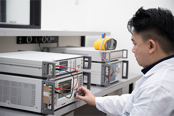
Unitest calibrates current transformers (metering class 0.1–1, protection class 5P/10P) against NMC-traceable current standards. SAC-SINGLAS accredited for industrial energy management and power quality monitoring.
CT calibration procedure
Calibration procedures differ between metering and protection CTs, but both require a calibrated current source traceable to NMC Singapore and a precision current comparator or ratio error meter to compare the CT's secondary output against the reference.
Metering CT calibration
- Connect the CT under test to a calibrated current source capable of delivering the rated primary current at the required accuracy. The source current is verified against the laboratory's NMC-traceable current reference standard.
- Connect the CT secondary to a calibrated ratio error meter (or precision current comparator) and the rated burden resistor. The burden connection is maintained throughout. Open-circuiting the secondary while primary current flows is a dangerous and lethal hazard due to the high voltages that develop.
- Measure ratio error and phase displacement at 5%, 20%, 100%, and 120% of rated primary current. Each measurement point is specified by IEC 61869-2 to confirm performance across the CT's operating range.
- For class 0.2S CTs, additionally test at 1% and 5% of rated current to verify accuracy at light load conditions. The "S" designation specifically addresses low-load measurement accuracy.
- Compare all results to the stated accuracy class limits. Any point exceeding the class limit is a calibration failure requiring the CT to be repaired, replaced, or reclassified to a lower accuracy class.
- Issue a calibration certificate stating measurement uncertainty, traceability to NMC Singapore, and the pass/fail status against the rated accuracy class.
Protection CT calibration
Measure composite error at ALF × rated current using a precision current comparator. The composite error combines ratio error and phase displacement into a single figure, testing whether the CT can accurately reproduce the fault current waveform. The test current for a 5P20 CT rated at 100A is 2,000A. Requiring a calibration laboratory with high-current generation capability and suitable safety arrangements for the test environment.
In-situ vs laboratory calibration
For installed CTs (especially metering CTs at utility intake points), laboratory calibration requires removing the CT from service. This means de-energising the feeder, breaking the metering circuit, and for SP Group metered circuits, involving SP Group in the process. Removal is invasive and has a downtime cost.
In-situ calibration using a portable CT analyser and a Rogowski coil primary reference is an alternative for large installed CTs where removal is impractical. The Rogowski coil clamps around the primary conductor without interrupting the circuit; it provides a reference measurement of primary current. The CT's secondary output is compared to the Rogowski coil reference to derive ratio error and phase displacement at operating load.
The limitations of in-situ calibration: the primary current level during the test depends on the actual load, which may not reach 100% or 120% of rated current; the Rogowski coil reference has its own uncertainty, which is typically higher than a laboratory current comparator; and the test cannot be performed at light load (below ~10% rated current) where the signal-to-noise ratio is poor.
For revenue metering purposes, SP Group requires laboratory calibration with traceable certificates. For industrial energy management CTs and power quality monitoring CTs where the requirement is internal quality system compliance (ISO 9001 clause 7.1.5.2 with SAC-SINGLAS recommended), in-situ calibration with a documented uncertainty budget is accepted and avoids production disruption.
Singapore regulatory context
SP Group regulates revenue metering in Singapore under the Electricity (Metering) Regulations. Revenue metering equipment must meet specified accuracy classes, and installation, testing, and sealing are performed by SP Group or their authorised agents. Any interference with a sealed metering installation is a criminal offence under the Electricity Act; replacement or recalibration of revenue metering CTs requires SP Group involvement.
For non-revenue metering (sub-metering for energy management, power quality monitoring, tenant billing), the customer's quality system requirements apply. ISO 9001:2015 clause 7.1.5.2 requires that measuring equipment used for monitoring and measurement conformity be calibrated against traceable standards with stated uncertainty. SAC-SINGLAS accredited calibration certificates are the standard mechanism for satisfying this requirement; an auditor who asks for traceability evidence will accept an accredited certificate on sight.
Singapore's EMA Power Factor Incentive Scheme penalises large consumers whose average power factor falls below specified limits. Accurate power factor measurement requires both voltage transformers (VTs) and current transformers to be within specification. A facility that is penalised for poor power factor (but whose metering CTs have drifted in phase displacement), may be paying unnecessary penalties. Calibration of the complete metering chain (CT and VT) confirms whether measured power factor reflects actual facility power factor.
For facilities pursuing ISO 50001 energy management system certification or undergoing energy audits under Singapore's Energy Efficiency Fund (EEF) schemes, calibrated sub-metering CTs are part of the evidence base for energy consumption measurement and verification. Auditors and verification engineers will ask for calibration certificates for the metering CTs that underpin the energy baseline and savings calculations.
Frequently asked questions
CT ratio error is the difference between a current transformer's actual transformation ratio and its rated ratio, expressed as a percentage. A 1000:1 CT with a +0.3% ratio error outputs 1.003A when the primary current is 1,000A, making a connected energy meter read 0.3% high. On a 500kW feeder running continuously, a 0.3% error equals around S$160 per year at Singapore commercial tariffs. Metering accuracy class limits (0.1% to 1%) define the maximum allowable ratio error to keep billing within acceptable bounds. Calibration verifies the actual ratio error at multiple current levels and confirms it stays within the class limit throughout the CT's rated operating range.
Metering CTs (accuracy class 0.1, 0.2, 0.2S, 0.5, 1) are designed for precision at normal operating currents. Typically 5% to 120% of rated primary current. Their calibration verifies tight ratio error and phase displacement limits at these normal current levels. Protection CTs (accuracy class 5P, 10P, PS) are designed to accurately reproduce fault currents that can be 5 to 20 times rated current. Their iron cores are designed to avoid saturation at fault currents; their calibration verifies composite error at the Accuracy Limit Factor times rated current. The two classes serve fundamentally different purposes: metering CTs measure energy accurately under normal conditions; protection CTs must faithfully reproduce fault waveforms so relays can operate correctly.
SP Group requires revenue metering CTs at utility intake points to meet accuracy class 0.2S or better. Class 0.2S specifies a maximum ratio error of ±0.2% across a wide current range (1% to 120% of rated current), making it suitable for loads that vary substantially through the day. For sub-metering within a facility (tenant energy metering, department cost allocation), class 0.5 is commonly used and accepted by most energy management systems. Class 1 is acceptable for general monitoring and power quality indication where billing accuracy is not the primary requirement. Always confirm the specific requirement with SP Group or your energy management system provider before specifying CT accuracy class for a new installation.
CT burden is the impedance of the connected secondary circuit. The meters, relay coils, and connecting cables. Every CT is rated at a specified VA burden (e.g. 2.5VA, 5VA, 10VA). If the actual connected burden exceeds the rated burden, the CT's magnetising current increases, pushing ratio error and phase displacement above the class limits. A class 0.2 CT rated at 2.5VA burden may perform only to class 0.5 accuracy when 10VA of meters and cable resistance are connected. This is a common source of metering error in older installations where additional monitoring equipment has been added without reassessing the CT burden. Calibration at actual site burden (not just rated burden), reveals whether the CT is performing within its class under real operating conditions.
In-situ CT calibration is possible using a portable CT analyser and a Rogowski coil as the primary current reference. The Rogowski coil clamps around the primary conductor without interrupting the circuit, providing a reference measurement. The CT's secondary output is compared to the Rogowski coil reference to derive ratio error and phase displacement at the current level flowing at the time of test. For revenue metering CTs at SP Group metering points, SP Group requires laboratory calibration with traceable certificates, in-situ testing is not accepted for these critical billing metering points. For industrial energy management CTs and power quality monitoring CTs, in-situ calibration is accepted and avoids the downtime of feeder de-energisation and CT removal.
Phase displacement is the angle between the secondary current phasor and the primary current phasor (reversed), measured in minutes of arc. A perfect CT has zero phase displacement. For unity power factor loads, phase displacement has negligible effect on active power (kW) measurement. For loads with a lagging power factor (common with induction motors in Singapore industrial facilities), phase displacement adds directly to error in reactive power (kVAr) and power factor measurement. A CT with 30 minutes phase displacement on a 0.8 power factor load can cause significant error in power factor calculations, affecting PFC controller operation, maximum demand tariff calculations under SP Group's demand charge, and compliance with EMA's Power Factor Incentive Scheme.
Yes. Unitest calibrates metering current transformers (accuracy class 0.1, 0.2, 0.2S, 0.5, 1) and protection current transformers (accuracy class 5P, 10P) against NMC-traceable current standards. Metering CT calibration verifies ratio error and phase displacement at 5%, 20%, 100%, and 120% of rated current, plus 1% and 5% for class 0.2S. Protection CT calibration verifies composite error at the Accuracy Limit Factor times rated current. Calibration is conducted under SAC-SINGLAS accreditation (no. LA-2023-0845-C). Certificates state measurement uncertainty and are suitable for industrial energy management audits, ISO 9001 clause 7.1.5 compliance, and power quality monitoring programs. Contact us to confirm scope coverage for your specific CT ratings and accuracy classes.

Unitest Instruments Pte. Ltd. is a SAC-SINGLAS accredited calibration laboratory (ISO/IEC 17025, no. LA-2023-0845-C) based in Singapore. We calibrate electrical, temperature, pressure, humidity, and related instruments (including current transformers for metering and protection), for manufacturers, service providers, and regulated industries across Singapore and the region.
Current transformer calibration (metering and protection class), SAC-SINGLAS accredited
Ratio error and phase displacement calibration against NMC-traceable current references. Industrial energy management audit-ready.
Verifiable at sac.gov.sg · LA-2023-0845-C