
Key takeaways
- Clamp meters measure AC current non-contact by sensing the magnetic field around a conductor. Ideal for large cables, busbars, and live circuits where opening the circuit is impractical.
- Multimeters measure current in series and can measure DC current accurately. Essential for low-current circuits, electronics troubleshooting, and any measurement where the clamp jaw would not fit.
- Most clamp meters include voltage and resistance modes, making them a practical all-in-one site tool, but their current accuracy at low ranges (below 1A) is typically far worse than a multimeter's milliamp function.
- Both instruments require periodic calibration. Clamp meters for both the jaw (CT linearity and accuracy) and the voltage/resistance functions; multimeters for all measurement functions across the specified ranges.
- For Singapore ISO 9001 and safety compliance programmes, both instruments are controlled instruments that must appear in your calibration register with current, traceable certificates covering every function in use.
The core distinction: circuit interruption vs non-contact
The single most important difference between a clamp meter and a multimeter is not the brand, not the display resolution, and not the number of measurement modes. It is whether the instrument requires you to break the circuit to measure current.
A multimeter's current function works by placing the meter in series with the load. The circuit must be opened at a convenient point, the test leads inserted to complete the path through the meter's internal shunt, and the reading taken. The meter is then removed and the circuit reconnected. This sequence is standard practice in electronics, control circuit work, and any application where the current is low enough to be within the meter's range. Typically 10A maximum for most multimeters. It is safe, accurate, and appropriate for the applications it was designed for.
A clamp meter's current function works entirely differently. The jaw (containing a current transformer core), is opened, placed around a single conductor, and closed. No contact with the conductor is made. No circuit interruption is needed. The current flowing through the conductor produces a magnetic field proportional to its magnitude, and the CT core in the jaw measures that field to derive the current value. The circuit never stops working; the technician never touches a live terminal.
In practice, consider a live 400V distribution panel measuring load current on a 100A circuit breaker output. A multimeter cannot do this safely. Its 10A fused input would blow instantly, and inserting probes into a live 400V busbar is an arc flash hazard under any safety protocol. A clamp meter jaws around the cable in under three seconds, reads the current, and is withdrawn. No shutdown required, no circuit interruption, no direct contact with a live conductor. That is the defining practical difference, and it explains why the clamp meter is the primary site tool for electrical maintenance work wherever current measurement is involved.
The tradeoff is accuracy at low currents. The same CT jaw optimised for 600A has poor resolution when the actual current is 0.3A. A multimeter's in-series milliamp range can resolve currents a hundred times smaller with better accuracy. Both instruments have their place; neither replaces the other completely.
How a clamp meter works. The current transformer principle
Understanding why a clamp meter works the way it does (including its limitations), requires a brief look at the physics of the current transformer (CT) that forms the heart of the jaw.
A current transformer works on exactly the same principle as a power transformer: a changing current in a primary winding induces a proportional current in a secondary winding, scaled by the turns ratio. In a clamp meter, the conductor being measured is the primary. A single-turn "winding" carrying the full line current. The jaw is the transformer core, typically made from a ferromagnetic material with high permeability. The secondary winding is a coil wound around the core inside the jaw, feeding the meter's measurement circuit.
If the line current is 100A AC, and the secondary has 1000 turns, the secondary current is 100A ÷ 1000 = 0.1A. A manageable signal the meter's circuitry can measure accurately. The meter then multiplies back up by the turns ratio to display 100A. This is why partial jaw closure produces a reading error: the transformer relies on the core forming a complete magnetic circuit around the conductor. If the jaw is not fully closed, there is an air gap in the core. Air has much lower magnetic permeability than the core material, so much of the magnetic flux leaks rather than being channelled through the secondary winding. The reading drops and the uncertainty grows. Always ensure the jaw fully snaps closed, and ensure the conductor passes through the centre of the jaw (not pressed against one side) for the most accurate result.
Split-core vs solid-core jaws. Most handheld clamp meters use a split-core jaw. The two halves open and close around the conductor. Solid-core clamp meters (where the conductor must be threaded through a fixed window) offer better accuracy, particularly at low currents and high frequencies, but require the circuit to be de-energised for installation. They are common in permanent power monitoring installations and precision current measurement applications.
AC only vs AC/DC. Standard clamp meters measure AC current only. The CT principle depends on a changing (alternating) magnetic field. DC produces a static field, and the CT core saturates rather than responding linearly. There is simply no output to measure. AC/DC clamp meters incorporate a Hall effect sensor alongside the CT. The Hall effect device responds to static magnetic fields by producing a proportional voltage, enabling DC current measurement. AC/DC capable clamp meters are more expensive, require zero-adjustment before use, and have somewhat wider uncertainty on the DC function. If you work on solar PV, battery storage, EV charging, or DC variable speed drives, verify your clamp meter is rated for DC before relying on it for current measurement.
Why low-current accuracy suffers. The CT jaw is optimised for the instrument's rated current range, typically 600A or 1000A. At those currents, the core is working in its efficient operating region and the signal-to-noise ratio is good. At 1A (one-sixth of one percent of a 600A range), the magnetic field in the core is extremely weak. The secondary current is a fraction of a milliamp. Noise, core non-linearity at low flux densities, and thermoelectric effects in the measurement chain all become proportionally significant. A 600A clamp meter measuring 0.5A might have an error of ±0.5A. Meaning the actual current could be anywhere between 0 and 1A. A multimeter measuring the same 0.5A on its milliamp range might have an error of ±2mA. For any sub-1A measurement where accuracy matters, use a multimeter.
How a multimeter measures current, and the safety considerations
A multimeter measures current by placing a precision low-resistance shunt (a calibrated resistor), in the current path. Current flowing through the shunt produces a proportional voltage drop across it, which the meter's voltmeter circuit measures and converts to a current reading using Ohm's law. This is why the multimeter must be inserted in series with the load: there must be a complete current path through the shunt.
The practical consequence is that the circuit must be opened, the meter's current terminals inserted, and the reading taken with the meter in the live circuit path. This is fine for most electronics work and control circuit applications. It becomes dangerous (and often impractical), on high-current live circuits.
The 10A ceiling. Most handheld multimeters have a maximum current input of 10A, occasionally 20A on higher-end models. The shunt is designed for these currents; beyond that, the meter's input fuse blows, and on some older designs, the shunt itself can be damaged. Connecting a standard multimeter to a 100A circuit will blow the fuse before a reading is obtained, and if the technician connects the current leads to a high-voltage source rather than in series (a common novice mistake), the result is an immediate short circuit that can cause severe arc flash.
The fuse matters more than most technicians realise. The current input on a multimeter is protected by an internal high-interrupting-capacity (HRC) fuse rated for the current range and the available fault current of the circuit. When a multimeter is connected correctly (in series with a current-limited circuit), the fuse is not stressed. But if the current terminals are accidentally connected across a voltage source (placing the meter in parallel rather than series), the meter presents a very low resistance path and a very large fault current flows. The fuse must interrupt this current before it damages the meter and, more critically, before it causes an arc flash that could injure the technician. On cheap multimeters, the fuse is rated for only a few hundred amps interrupting capacity. On quality instruments like the Fluke 87V, the input fuse is rated for the full fault current of the measurement category. This is one reason cheap multimeters on live circuits are a genuine safety risk.
Milliamp and microamp ranges. The multimeter's strength at low currents is its milliamp function. Typically a separate input terminal rated at 400mA or 600mA, with resolution down to 0.01mA or better. For control circuit current checks (4–20mA process loops, PLC analogue input verification), for battery drain analysis (finding microamp leakage currents in idle electronics), and for winding continuity checks requiring accurate resistance or sub-milliamp excitation, the multimeter is the only appropriate instrument. These are measurements a clamp meter physically cannot make with useful accuracy.
Safe operating sequence. Always begin with voltage measurement (confirm the circuit voltage before inserting current probes. Never measure resistance on a live circuit), the meter applies its own test current through the resistance function; applying it to a live conductor will damage the meter and may create a hazard. Switch the meter from voltage to current mode only after confirming the circuit is open and the current path is ready to accept the meter in series. This sequence is not optional; it is fundamental electrical safety practice.
Where clamp meters win. High-current live circuit work
The clamp meter's domain is any situation involving currents above 10A on a circuit that cannot or should not be interrupted. In Singapore's commercial building and industrial contexts, this covers the majority of M&E maintenance work.
Motor current monitoring. Verifying that a motor is drawing current within its nameplate rating (and that all three phases are balanced), is a routine maintenance check. On a 15kW three-phase motor running at 400V, the full-load current is approximately 27A per phase. A clamp meter jaws around each phase conductor in turn to take the reading. No shutdown, no circuit interruption, no service downtime.
Distribution panel load balancing. A facility engineer auditing load distribution across a main switchboard takes clamp meter readings on every outgoing circuit breaker to identify overloaded or imbalanced phases. This audit could involve thirty or more measurements. Doing it with a multimeter in series would require switching off each circuit in turn and rewiring, a day's work. With a clamp meter it takes under an hour, live, without affecting any load.
HVAC compressor and chiller loads. Air conditioning compressors draw high starting currents (often five to seven times running current) that are important to monitor for mechanical health. Clamp meters with data-hold or peak-capture functions can capture inrush current at startup. Information impossible to obtain without either a non-contact instrument or a permanently installed current transducer.
Busbar current verification. On LV busbar systems, the busbars themselves are often large copper bars carrying hundreds of amps. A clamp meter with a jaw large enough to fit around the busbar (some models have extended jaws for this purpose) can verify distribution and loading without any panel shutdown.
Power quality clamps. Advanced clamp meters with power quality functions can measure true RMS current, power factor, harmonics, and apparent power on a live circuit. This is essential for energy auditing and troubleshooting power factor correction equipment in Singapore commercial buildings. Work that must be done live and cannot involve circuit interruption.
Earth leakage current. Specialised milliamp clamp meters (zero-flux type or leakage clamps) can measure earth leakage currents as small as 1mA by clamping around all active conductors together. The net current from a balanced circuit is zero; any earth fault current appears as the difference. These instruments are used for testing residual current device (RCD) installations and for diagnosing nuisance tripping. Work that requires a live circuit to produce any reading at all.
Where multimeters win. Accuracy at low currents and DC
The multimeter's domain is any measurement requiring precision at low currents, DC current measurement, the full range of resistance and continuity functions, or measurements on circuits small enough to be interrupted safely.
Electronics and PCB work. Current consumption of a microcontroller circuit, leakage current through a transistor, the drain current of a MOSFET gate driver. These are all in the microamp to milliamp range where a clamp meter is useless. On a PCB, you would not fit a clamp jaw around a single PCB trace anyway. The multimeter in milliamp mode, inserted via the break point in a current path, is the only practical tool.
4–20mA process loop verification. Industrial process control uses standardised 4–20mA current loops where 4mA represents zero percent of range and 20mA represents 100%. A transmitter indicating 50% of range should produce exactly 12mA. Verifying this requires a milliamp-capable meter in series with the loop. A function a clamp meter cannot perform accurately enough to be useful at this current level.
DC current measurement, solar and battery systems. Without an AC/DC clamp meter, measuring DC current on a solar PV string or battery bank requires a multimeter in series. Even with an AC/DC clamp, the Hall effect DC function on most mid-range clamp meters has wider uncertainty than a multimeter's in-series DC current range. For accurate DC energy accounting (verifying panel output, battery state of charge monitoring, EV charging current verification), a precision multimeter is the more reliable choice.
Resistance measurement and continuity testing. Both instruments have ohmmeter functions, but the multimeter's resistance measurement is typically more accurate across a wider range and includes features like relative measurement, diode testing, continuity beeper, and capacitance measurement on mid-range models. Motor winding DC resistance measurement (important for detecting shorted turns and comparing phase-to-phase), requires a four-wire (Kelvin) measurement on the best instruments; some Fluke precision multimeters support this. Clamp meters rarely do.
Control circuit and PLC I/O verification. Verifying that a PLC digital output is correctly driving a relay coil, or that an analogue output is producing the expected voltage, involves measurements in the millivolt to 24V range with the circuit in normal operating state. A multimeter's voltage accuracy at these signal levels is typically better than a clamp meter's, and the ability to use fine-tipped probes on control terminal blocks makes the multimeter the preferred tool.
Full specification comparison
The table below compares the practical specification of a quality clamp meter against a quality general-purpose multimeter across all major parameters.
| Feature | Clamp Meter (e.g. Fluke 376 FC) | Multimeter (e.g. Fluke 87V) |
|---|---|---|
| Current measurement method | Magnetic clamp jaw (CT transformer). Non-contact | Series (circuit must be opened) |
| AC current range | 600A–2000A typical; some models to 2000A | Typically 10A max (some 20A) |
| AC current measurement | Yes. Primary function | Yes (in series, up to rated input) |
| DC current measurement | Limited. AC/DC models only (Hall effect) | Yes (in series). Standard function |
| Low-current accuracy (<1A) | Poor. Resolution limitation of CT at low flux | Good. Milliamp range available |
| Circuit interruption needed? | No, for current only | Yes, for current only |
| Voltage measurement | Yes. Standard function | Yes. Standard function |
| Resistance measurement | Yes. Standard function | Yes. Standard function |
| Capacitance / frequency | Varies by model | Common on mid-range models |
| Safety rating (typical) | CAT III 600V / CAT IV 600V | CAT III 1000V / CAT IV 600V (Fluke 87V) |
| Form factor | One-handed jaw tool | Two-hand probes |
| Typical primary use | Live panel current checks, motor loads, HVAC | Electronics troubleshooting, resistance, DC |
| Calibration parameters | Current (clamp jaw), V, R | V, I (in-series), R |
| Calibration cost (relative) | Slightly higher (more parameters including jaw) | Standard |
The safety rating row deserves specific attention. CAT IV 600V is the rating for equipment connected to the service entrance. The point where the supply enters the building from the utility, or outdoor distribution equipment including outdoor substations. Many clamp meters carry CAT IV ratings specifically because they are used at high-current points close to the service entrance. Most handheld multimeters are rated CAT III 1000V. Appropriate for fixed installation switchgear inside buildings, but not for work at the utility entry point. Using an under-rated instrument at the service entrance creates risk of meter destruction and severe arc flash injury if a fault occurs. Always match the instrument's CAT rating to the work location, not just the voltage.
Calibration requirements. How they differ between the two instruments
Both clamp meters and multimeters are controlled instruments in an ISO 9001 programme. Both must appear in the calibration register, both require periodic calibration with traceable certificates, and both require an assigned calibration interval with a documented basis. The differences lie in what a complete calibration covers for each instrument type.
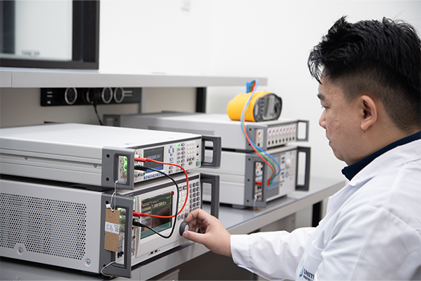
Multimeter calibration. A multimeter calibration covers all the measurement functions the instrument is used for: AC and DC voltage across the relevant ranges, AC and DC current (in series, using a calibrated current source and a series connection), and resistance across the relevant ranges. Some calibrations also cover frequency, capacitance, and temperature if the meter has those functions and they are used. The calibration is performed by connecting the instrument to a calibrated reference source and measuring the deviation between the instrument's reading and the reference value. Measurement uncertainty is stated for each point and range.
Clamp meter calibration, why the jaw is separate. A clamp meter calibration has two distinct components. The first is the same as a multimeter: voltage and resistance functions calibrated in the conventional way. The second (and the component that many labs skip), is the jaw (CT function) calibration.
Calibrating the jaw requires a dedicated AC current source capable of producing stable, known currents at the current levels the meter is rated for , 100A, 300A, 600A, or higher. The current source is itself traceable to NMC. The clamp meter's jaw is placed around the reference conductor carrying the known current, and the meter's reading is compared against the reference. Calibration is typically performed at multiple points across the range (commonly at 10%, 50%, and 100% of the rated current), because CT accuracy varies with the level of excitation.
The jaw calibration cannot be performed with a standard bench calibrator of the type used for voltage and resistance. It requires a current transformer calibration rig. Many smaller calibration providers do not have this equipment, and as a result, they calibrate only the voltage and resistance functions of a clamp meter and omit the jaw entirely. The certificate they issue may not make this omission obvious. It may simply state the parameters that were calibrated, and if you do not specifically look for "current (clamp jaw)" on the scope, you will not notice the gap.
For an ISO 9001 compliance programme, this matters directly. If your clamp meter is used for current measurement (which is the primary reason most people own a clamp meter), and the jaw has not been calibrated, that measurement function has no traceable calibration backing it. An auditor reviewing your calibration certificates and noting that the instrument's primary function is not on the calibration scope will raise a non-conformance. The remedy requires sending the instrument to a lab that can calibrate the jaw, which is not all labs.
What to look for on a clamp meter calibration certificate that covers the jaw:
- A clearly listed current (AC) function with measurement points, e.g. 60A, 300A, 600A for a 600A clamp
- The nominal current value, the meter's reading, and the deviation for each point
- A stated expanded measurement uncertainty for each current point
- The accreditation scope reference confirming current (AC) is within the lab's accredited scope
If the certificate lists only voltage (V AC, V DC) and resistance, the jaw was not calibrated. Ask explicitly before sending instruments, and confirm the lab has the current source capability for your meter's rated range.
Calibrate both your clamp meters and multimeters. All functions, accredited certificates
Unitest calibrates clamp meters (jaw + voltage + resistance) and multimeters against NMC-traceable references. Certificates cover all calibrated functions. Ready for ISO 9001 and safety audits.
Building your calibration register: what to record for each instrument type
A calibration register is the backbone of an ISO 9001 clause 7.1.5 compliance programme. For both clamp meters and multimeters, the minimum record for each instrument should include the following fields.
For all electrical measuring instruments: instrument ID (your internal tag), manufacturer and model, serial number, measurement function(s) in use, current calibration status (in or out of calibration), calibration due date, calibration interval, certificate reference number, and the calibrating lab's name and accreditation number.
Additional fields specific to clamp meters: note explicitly which functions were calibrated on the most recent certificate (jaw (AC current), V AC, V DC, resistance), and the current ranges covered. Many calibration programmes simply record "pass" against a clamp meter without noting whether the jaw was in scope. If the jaw was not calibrated, the register entry should flag this as a known limitation with a risk-based justification if the current function is not used, or as a gap action if it is.
Additional fields specific to multimeters: note the measurement ranges covered by the calibration. A multimeter may have voltage ranges from 200mV to 1000V; if your application uses only the 600V range, a calibration covering only that range is technically sufficient, but if you later use the 200mV range without recalibrating for it, the compliance gap opens. Recording what was and was not covered at each calibration allows you to audit this without re-reading every certificate.
The scope gap issue is more common than most quality managers realise. Sending an instrument to a lab and receiving back a certificate does not guarantee all functions are covered. It guarantees the functions the lab chose to calibrate are covered, within their accredited scope. Establishing a clear written scope of calibration when you send the instrument, and verifying the returned certificate matches that scope, is the only reliable way to avoid gaps.
Choosing the right instrument for your application
Most experienced electricians and instrument technicians carry both a clamp meter and a multimeter, because the applications split cleanly between them. The decision framework below covers the most common situations.
Use a clamp meter when:
- The current is above 10A and the circuit cannot or should not be interrupted
- You are working in a live distribution panel or on live cables
- You are monitoring motor current, transformer loading, or distribution board balance
- Speed matters. You are reading multiple circuits in sequence
- You need peak capture or power quality functions on a live circuit
Use a multimeter when:
- The current is below 1A and accuracy matters. Milliamp or microamp ranges
- You are measuring DC current and do not have an AC/DC clamp meter
- You are working on control circuits, PCBs, or electronics
- You need milliamp range for 4–20mA loop verification
- You need capacitance measurement, diode testing, or temperature measurement
- You need the highest available accuracy on resistance measurement
For the majority of Singapore M&E maintenance technicians, the clamp meter is the first tool used on any job involving power circuits. It provides immediate non-contact current readings that inform every subsequent decision. The multimeter comes out for control wiring, commissioning verification, troubleshooting signal-level circuits, and any DC measurement. Having both instruments properly calibrated, with both on the calibration register, is the baseline for a compliant instrument programme.
Recommended models for Singapore industrial use
For most Singapore industrial and commercial electrical maintenance applications, the following instruments represent the practical standard at each tier.
Clamp meters: The Fluke 376 FC is a well-regarded general-purpose clamp meter for industrial work , 1000A AC/DC, iFlex flexible current probe compatibility for large conductors that a standard jaw cannot fit around, Bluetooth data logging, and CAT IV 600V rating. For applications requiring only AC current to 600A without the DC function, the Fluke 374 FC offers the same form factor at a lower price point. The Hioki CM4372 is preferred for applications requiring higher accuracy on the CT function. Hioki's precision clamp meters are widely used in calibration and energy audit work where tighter current uncertainty is needed.
Multimeters: The Fluke 87V remains the industry reference for general-purpose multimeters. True RMS, milliamp range, frequency measurement, temperature with thermocouple input, CAT III 1000V / CAT IV 600V safety rating, and a robust build record over many years of industrial use. For applications requiring wider current range or higher precision on resistance, the Fluke 289 adds data logging and a higher current range. Both are well-supported in Singapore with available calibration at multiple SAC-SINGLAS accredited labs including Unitest.
Unitest stocks and calibrates Fluke clamp meters and multimeters. If you are unsure whether your current instruments' calibration certificates cover the functions you use (particularly the jaw calibration on clamp meters), contact us and we can review the certificates against your application requirements before you next send instruments for calibration.
Frequently asked questions
Not completely. A clamp meter covers most site electrical work well. AC voltage, resistance, continuity, and high-current AC measurement without circuit interruption. But it cannot replace a multimeter for low-current DC circuits, milliamp ranges used in electronics, accurate sub-1A current readings, or situations where the jaw physically cannot fit around a conductor. Most experienced electricians carry both: the clamp meter as their primary site tool and a multimeter for precision, DC, and electronics work. If you can own only one instrument and your work is entirely in the power distribution domain with no sub-10A current work, a quality clamp meter with voltage and resistance functions covers most scenarios, but the milliamp limitation will eventually matter.
Standard AC-only clamp meters cannot measure DC current. The CT jaw operates on the principle of an alternating magnetic field, which DC does not produce. AC/DC clamp meters exist and use a Hall effect sensor to measure the static magnetic field produced by DC. If you work with solar PV systems, battery banks, DC drives, or EV charging equipment, you need an AC/DC clamp meter specifically. Verify the specification before purchasing or relying on readings. The DC clamp function has its own accuracy specification distinct from the AC CT function, and it requires a zero adjustment before use to null out Earth's background magnetic field. The zero adjustment step is commonly skipped, leading to systematic DC reading errors.
The standard starting interval for a clamp meter in regular industrial use is 12 months. If your clamp meter is used daily on high-current circuits, exposed to vibration or mechanical shock, or if it has been dropped, the interval should be reviewed and potentially shortened to 6 months. The instrument manufacturer's recommended interval is a reasonable baseline. Your calibration history data (whether the instrument has been found consistently within tolerance at successive calibrations), should inform whether you extend or shorten the interval over time. ISO 9001 clause 7.1.5 requires that intervals be documented and that the basis for the interval is justified. Automatic 12-month default is common, but documenting the reasoning and reviewing it periodically is what an auditor expects to see.
If you are using the clamp meter for current measurement and the jaw has not been calibrated, that current measurement is not traceable and has no stated uncertainty. This is a real gap in many calibration programmes. Some labs skip the jaw calibration because it requires a dedicated current source and they either lack the equipment or do not flag the gap to the customer. For an ISO 9001 controlled instrument, the calibration scope on the certificate must cover the measurement functions you actually use. If you use the clamp function, it must appear on the certificate with current points, deviations, and stated uncertainty. An auditor reviewing your calibration records will check whether the scope matches your instrument's operational use. A certificate that covers only voltage and resistance on a current clamp is a finding waiting to happen.
For live panel current measurement, a clamp meter is substantially safer. It requires no circuit interruption and no insertion of probes into live terminals. The risk of an accidental arc flash from misplaced probes, or of blowing the meter's input fuse on an oversized circuit, is eliminated. Multimeters, when used for current measurement in series, require the circuit to be opened and the meter inserted. A more hazardous operation on a live panel at distribution voltages. For voltage measurement, both instruments use probes on live terminals, and the risk profile is similar, provided the instrument is rated for the measurement category of the work (CAT III for indoor panel work, CAT IV for service entrance work) and the voltage level. In all cases, follow established safe work procedures. Appropriate PPE, single-hand technique, and confirmation of instrument rating before starting.
Singapore industrial supply is predominantly 3-phase 400V/230V. On a standard 100A three-phase distribution board, phase current under full load can reach 80–100A per phase; on main feeders to large M&E plants or chiller plants, 400A–800A is common. A clamp meter rated to 600A covers most sub-distribution panel work; 1000A or 2000A ratings are needed for main switchboard feeders and large transformer secondary outputs. For motor current measurement on single-phase circuits and standard sub-distribution work, a 400A or 600A clamp meter is typically sufficient. Select a range that keeps your expected reading in the upper half of the scale. A 600A clamp reading 60A is operating at only 10% of range where CT accuracy is weakest. For readings typically below 60A, a 200A clamp meter will give better resolution.
Unitest calibrates the clamp jaw (current transformer function) as well as the voltage and resistance functions. Calibration of the jaw is performed using a dedicated calibrated current source traceable to Singapore's NMC, with the clamp meter's jaw placed around the reference conductor at multiple current points. Typically 10%, 50%, and 100% of the rated nominal current. Measurement uncertainty is stated for each current point. The calibration certificate clearly lists all calibrated functions under our SAC-SINGLAS accredited scope. When you send a clamp meter to Unitest, confirm that jaw calibration is required in your submission. We will confirm capability and coverage for your specific model and rated current range before the calibration begins, and the returned certificate will reflect the full scope.

Unitest Instruments Pte. Ltd. is a SAC-SINGLAS accredited calibration laboratory (ISO/IEC 17025, no. LA-2023-0845-C) based in Singapore. We calibrate electrical, temperature, pressure, humidity, and related instruments (including clamp meters with full jaw calibration), for manufacturers, service providers, and regulated industries across Singapore and the region.
Calibrate your clamp meters and multimeters with full-function accredited certificates
Unitest calibrates clamp meters including jaw function and all voltage/resistance ranges, not just the easy functions. SAC-SINGLAS accredited, NMC traceable, audit-ready certificates.
Verifiable at sac.gov.sg · Acc. No. LA-2023-0845-C