
Key Takeaways
- 4 mA = 0% span (live zero); 20 mA = 100% span, any reading below 3.6 mA signals a fault, not a low process value.
- Current-mode signalling is immune to resistive voltage drops along cable runs, making it reliable over distances up to 1,000 m in most industrial installations.
- Two-wire loop-powered transmitters draw their operating power from the 4-20 mA loop itself. No separate supply wires are needed.
- Maximum loop resistance is determined by the formula R_max = (V_supply − V_transmitter_min) / 0.020. Exceeding this prevents the transmitter from reaching 20 mA.
- Calibration to ISO/IEC 17025 with traceability to Singapore's NMC is required for safety-critical and trade measurement applications under IEC 61511 and the Weights and Measures Act.
What Is the 4-20 mA Current Loop?
The 4-20 mA current loop is an analog transmission standard defined by IEC 60381-1 (Analogue signals for process control systems. Part 1: Direct current signals) and widely implemented across pressure, temperature, flow, and level transmitters. Unlike a voltage signal, which varies along a cable due to resistive losses (Ohm's Law: V = IR), a current signal is the same at every point in a series circuit. The current that flows out of the transmitter is identical to the current that arrives at the controller input, regardless of cable resistance. This fundamental property of series circuits makes current-mode transmission immune to the resistive losses that would corrupt a 0-10 V or 1-5 V voltage signal over long cable runs.
The standard defines a live zero of 4 mA rather than 0 mA. This choice (first established in the 1950s for pneumatic 3-15 PSI systems, then carried into electronic instrumentation), is the most consequential single design decision in process instrumentation. At 4 mA, the transmitter is signalling the minimum process value; at 20 mA, it is signalling the maximum. Any measured current below 3.6 mA (the IEC-defined under-range alarm threshold) indicates a broken wire, blown fuse, or failed transmitter rather than a genuine process reading at or below zero.
The 16 mA working range (20 − 4 = 16) provides a convenient linear mapping: each 1 mA step corresponds to 6.25% of span. The percentage of span is calculated as: % Span = (mA − 4) / 16 × 100. And the process value in engineering units is: PV = LRV + [(mA − 4) / 16] × Span, where LRV is the lower range value and Span = URV − LRV.
The Physics of Current-Mode Signalling
A 4-20 mA transmitter is, in electrical terms, a controlled current source. Its output stage maintains a constant current regardless of the load resistance in the loop, up to the transmitter's compliance voltage limit. The transmitter senses the process variable (pressure, temperature, flow, etc.) and adjusts its internal impedance to force exactly the right current to flow (from 4 mA at LRV to 20 mA at URV), through whatever resistance the loop presents.
This behaviour contrasts with a voltage source, which maintains a constant voltage while allowing current to vary with load. In a current source, the useful consequence is Kirchhoff's Current Law applied to a series loop: the same current flows through every element in the loop. A 250 Ω receiving resistor at the controller converts the current back to a voltage (1-5 V at 4-20 mA, by Ohm's Law), which the analogue input module reads with its ADC.
Noise Immunity: Why Current Wins Over Long Runs
Electromagnetic interference (EMI) from variable-speed drives, motor contactors, and switching power supplies induces voltage noise onto cable conductors. In a voltage-signal circuit (e.g. 0-10 V), even a 100 mV noise voltage represents 1% of full scale, a significant measurement error. In a 4-20 mA loop, the same 100 mV induced voltage would need to overcome the current source's output impedance (typically hundreds of kilohms) to alter the loop current; the resulting current error is negligible. This is why IEC 60381-1 specifies 4-20 mA as the preferred standard for cable runs beyond 30 m in industrial environments, and why it remains the default in Singapore's MRT infrastructure, petrochemical plants, and water treatment facilities.
| Signal Type | Typical Range | Max Practical Cable Run | EMI Immunity | Fault Detection |
|---|---|---|---|---|
| 4-20 mA current | 4–20 mA | Up to 1,000 m (depends on R_max) | Excellent | Yes (live zero) |
| 0-10 V voltage | 0–10 V | ~30 m (unshielded) | Poor–Fair | No |
| 1-5 V voltage | 1–5 V | ~10–20 m | Poor | Partial (1 V live zero) |
| Thermocouple (mV) | mV range | ~50 m (extension cable) | Very Poor | No |
| HART (4-20 mA + FSK) | 4–20 mA + digital overlay | Up to 3,000 m with repeater | Excellent | Yes + diagnostics |
Two-Wire, Three-Wire, and Four-Wire Configurations
The most significant wiring topology decision for any 4-20 mA installation is the choice between loop-powered (two-wire) and separately-powered (four-wire) transmitters. This choice affects wiring cost, hazardous-area compliance, and the calibration procedure.
Two-Wire (Loop-Powered) Transmitters
In a two-wire transmitter, the same two conductors carry both the DC supply voltage to the transmitter and the return signal current. The transmitter electronics are powered by the difference between the supply voltage and the voltage dropped across the loop resistances. At 4 mA (the minimum signal), the transmitter draws exactly 4 mA, which is also its minimum operating current. The transmitter's internal electronics must function on this small quiescent current; modern two-wire transmitters typically consume 3.5 to 3.8 mA of self-power, leaving 0.2 to 0.5 mA of margin. This constraint explains why two-wire transmitters generally offer lower measurement bandwidth and cannot drive LCD displays without additional power harvesting circuits.
The typical supply voltage for a two-wire loop is 24 V DC (per IEC 60381-1). The maximum loop resistance (including all wiring, connector, and barrier resistances), is calculated as: R_max = (V_supply − V_compliance_min) / I_max = (24 − 12) / 0.020 = 600 Ω for a transmitter requiring 12 V minimum compliance. Exceeding this resistance prevents the transmitter from reaching the 20 mA full-scale output.
Three-Wire Transmitters
Three-wire transmitters use a shared common (return) conductor for both the power supply negative and the signal return. The power supply positive and signal positive are on separate wires. This configuration reduces the loading on the signal path but is less common in modern field installations due to wiring complexity.
Four-Wire Transmitters
Four-wire transmitters have completely independent power supply and signal circuits. Two wires carry 24 V DC (or 110/230 V AC for line-powered units) to the transmitter's power supply, and two separate wires carry the 4-20 mA output signal back to the controller. This arrangement allows the transmitter electronics to consume as much power as needed (analysers, multi-variable transmitters, and weighing systems often require 500 mA or more) without affecting the signal quality. Four-wire transmitters cannot be used in two-wire-only intrinsic safety (IS) barriers.
Need your 4-20 mA transmitters calibrated with a traceable certificate?
Unitest Instruments calibrates pressure, temperature, flow, and level transmitters across their full 4-20 mA output range. Certificates accepted by ISO 9001, IEC 61511, and MOM auditors across Singapore.
Calibrating a 4-20 mA Transmitter: Step-by-Step
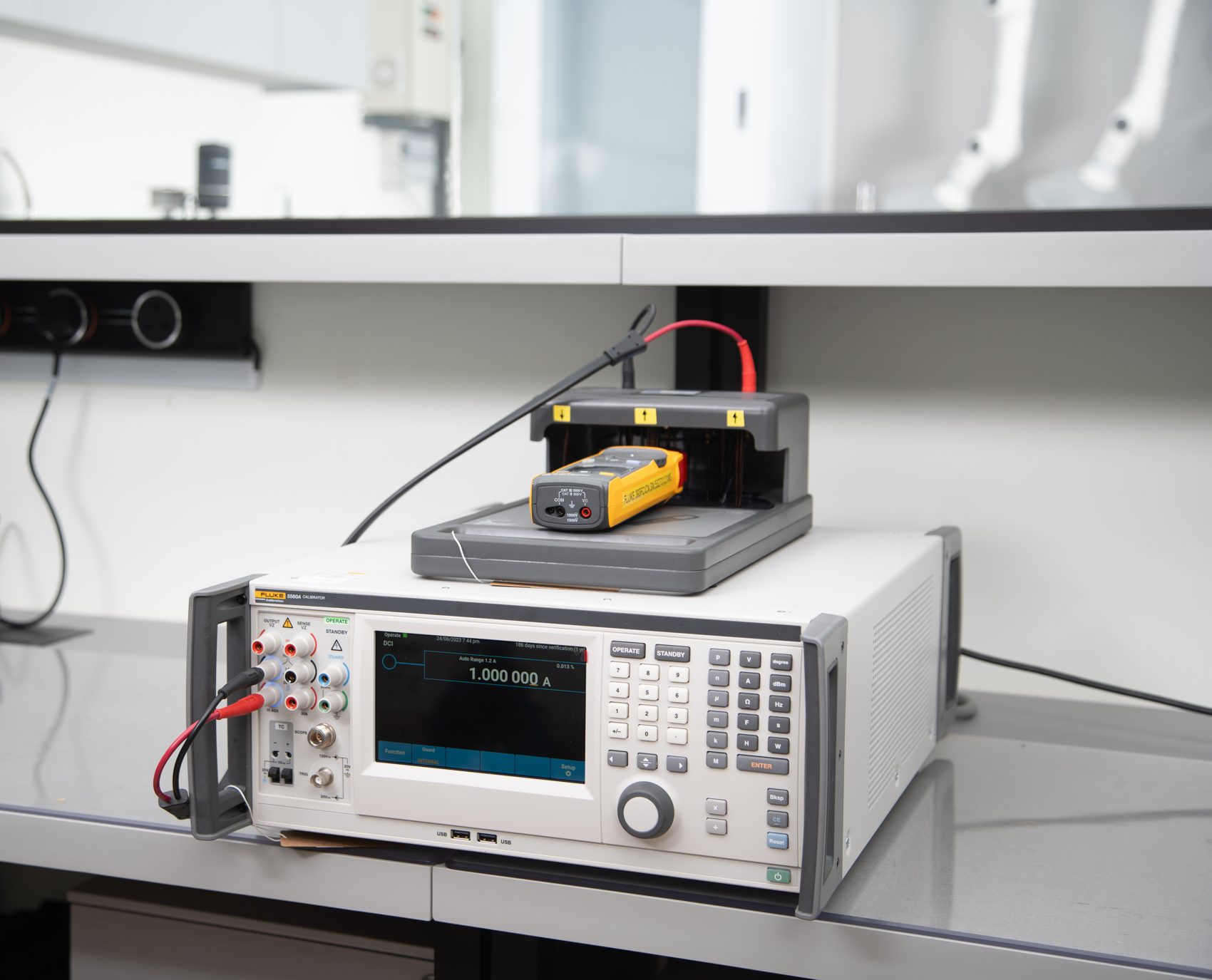
Calibration of a 4-20 mA transmitter involves applying a traceable reference input at the sensing element and verifying (or adjusting), the current output at multiple points across the range. As explained in our guide on what a calibration certificate contains, a valid calibration must include reference standards traceable to national measurement standards (in Singapore, to the NMC under A*STAR).
Equipment Required
- A process calibrator capable of sourcing or simulating the reference input (pressure, temperature, or other measurand), e.g. Fluke 725, Druck DPI 620 Genii, or equivalent with current traceable calibration.
- A calibrated current meter or a process calibrator with 4-20 mA loop measurement mode (resolution ≥ 0.001 mA).
- A 24 V DC loop supply (if the transmitter is removed from service) or the existing loop supply if calibrating in situ.
- A 250 Ω precision resistor for HART communication (if applicable).
The Five-Point Calibration Procedure
Apply input at five ascending test points (0%, 25%, 50%, 75%, and 100% of span), and record the mA output at each point. Repeat descending from 100% to 0%. This as-found "5-up/5-down" dataset reveals both accuracy error and hysteresis. Compare each recorded mA value against the ideal using the formula: mA_ideal = 4 + [(% span / 100) × 16]. The permissible error depends on the transmitter's accuracy class; a typical smart transmitter specifies ±0.1% of span (±0.016 mA), while a basic analog transmitter may specify ±0.5% of span (±0.08 mA).
If the as-found error exceeds the specification, adjust the transmitter's zero trim (LRV adjustment) and span trim (URV adjustment) and re-verify. Record the as-left values on the calibration record. The measurement uncertainty of the calibration itself must be small relative to the transmitter's specification. The uncertainty ratio (TUR, Test Uncertainty Ratio) should be at least 4:1 per ILAC-G8 and OIML R 34 guidance.
HART Protocol: Digital Intelligence over the 4-20 mA Wire
The Highway Addressable Remote Transducer (HART) protocol, standardised in IEC 62591 and maintained by the FieldComm Group, overlays a digital communication signal onto the 4-20 mA loop without disrupting the analog measurement. HART uses Frequency Shift Keying (FSK) at 1,200 bps (a 1,200 Hz tone for a logical "1" and a 2,200 Hz tone for a logical "0"), superimposed on the DC loop current. Because the FSK signal is AC-coupled and averages to zero, it does not alter the DC current value read by the controller's analog input.
HART allows a handheld communicator or PC-based asset management system to read the transmitter's process variable, diagnostic status, engineering units, range settings, and device information. All over the existing two-wire loop. This capability is critical for predictive maintenance programs in Singapore's process industries: a HART-capable transmitter can report its sensor temperature, detected membrane rupture, or self-diagnostic fault codes without any additional wiring. For calibration purposes, HART allows zero and span trim to be performed digitally via the communicator, with a full audit trail stored in the transmitter's non-volatile memory.
Common Faults and How to Diagnose Them
Understanding fault signatures is as important as understanding normal operation. The following faults are encountered regularly in Singapore's tropical, high-humidity industrial environment.
1. Open Circuit (Current = 0 mA or Below 3.6 mA)
An open circuit breaks the series loop, driving current to zero. The controller reads below 3.6 mA and should trigger a "wire break" alarm. Common causes: corroded terminal connections (especially in outdoor junction boxes exposed to Singapore's humidity and salt air), a blown fuse in the loop supply, or a failed transmitter output stage. Diagnosis: measure voltage across the suspected open point. Full supply voltage (typically 24 V) across an open terminal confirms the break location.
2. Saturated Output (Fixed at 3.6 mA or 21 mA)
Many smart transmitters drive their output to 3.6 mA (NAMUR NE 43 under-range alarm) or 21.0 mA (over-range alarm) when a sensor fault is detected. A reading stuck at exactly these values is almost always a transmitter-reported fault rather than a genuine process condition. Read the HART diagnostic message or check the transmitter's LCD to identify the fault code.
3. Ground Loop (Erratic or Offset Reading)
A ground loop forms when the loop circuit has more than one path to earth potential. A difference in ground potential between the transmitter location and the control room (even 100 mV), drives a spurious current through the loop, creating a DC offset error. Ground loops are particularly common in Singapore's industrial estates where multiple earthing systems converge. Diagnosis: measure the voltage between the two loop conductors at the controller input with the transmitter disconnected; any reading other than 0 V indicates a ground loop. Solution: use a 4-20 mA signal isolator (galvanic isolator) to break the ground path while passing the signal current.
4. Excessive Loop Resistance
As cable length increases, so does the total loop resistance (conductor resistance is typically 13–20 Ω per 100 m for 0.5 mm² to 1.0 mm² cable). If total resistance exceeds R_max, the transmitter cannot reach 20 mA at full scale. The output saturates at some intermediate current value. Diagnosis: measure total loop resistance with the transmitter disconnected; compare against the transmitter's compliance specification. Solution: increase supply voltage (if within transmitter limits), reduce loop resistance by upgrading to larger cable, or add a local loop repeater/booster.
5. Moisture Ingress and Insulation Leakage
Singapore's ambient relative humidity regularly exceeds 85%, and tropical rain events expose outdoor junction boxes and conduit entries to standing water. Moisture between loop conductors creates a leakage resistance in parallel with the load, diverting a fraction of the loop current and reducing the effective signal at the controller input. A 10 kΩ leakage resistance in parallel with a 250 Ω load creates approximately 2.5% reading error at full scale. Diagnosis: use a 500 V insulation resistance tester (megohmmeter) between loop conductors and earth; readings below 1 MΩ indicate significant leakage. Resolution: dry the termination, apply dielectric grease, and seal conduit entries against future ingress.
Calibration Intervals and Traceability in Singapore
Determining how often to calibrate a 4-20 mA transmitter requires balancing process risk against calibration cost. Our detailed guide on calibration intervals covers the risk-based methodology in full. For 4-20 mA transmitters in process control applications, a one-year calibration interval is common for non-critical loops; SIL-rated safety loops typically require six-monthly or annual calibration with formal documentation as part of the Safety Instrumented Function (SIF) proof-test procedure under IEC 61511.
All calibration results must be traceable to national measurement standards. In Singapore, the National Metrology Centre (NMC) under A*STAR maintains the primary standards for electrical quantities, pressure, temperature, and flow. The measurands that feed into 4-20 mA transmitter calibration. SAC-SINGLAS (Singapore Accreditation Council – Singapore Laboratory Accreditation Scheme) operates the laboratory accreditation system under ISO/IEC 17025. Unitest Instruments holds accreditation number LA-2023-0845-C, covering calibration of electrical measurement instruments, pressure gauges, temperature sensors, and associated transmitters.
An ISO/IEC 17025 calibration certificate from an accredited laboratory provides the documented evidence of traceability required by ISO 9001 clause 7.1.5, IEC 61511 clause 11.4 (safety instrumented systems), and the Singapore Weights and Measures Act (Cap. 349) for trade measurement instruments. Certificates from non-accredited laboratories (however well-intentioned), do not satisfy these requirements and will be rejected by third-party auditors. For more on what a valid certificate must contain, refer to our article on accredited vs non-accredited calibration.
Frequently Asked Questions
A 4-20 mA current loop is an analog signalling standard in which 4 milliamps represents the minimum process value (0% of span) and 20 milliamps represents the maximum process value (100% of span). The non-zero live zero at 4 mA allows the control system to distinguish a genuine zero reading from an open-circuit fault, which would drive the current to 0 mA. Any reading below 3.6 mA is treated as a fault condition, not a valid process measurement.
The 4 mA live zero serves three purposes. First, it provides fault detection: a reading below 3.6 mA indicates a broken wire or transmitter failure rather than a genuine zero-process condition. Second, the 4 mA provides power to a two-wire transmitter without any separate supply wires. The transmitter draws its operating current from the loop itself. Third, it separates the signal band (4-20 mA) from the fault band (0-3.6 mA), allowing controllers to trigger alarms automatically without any additional hardware.
A two-wire (loop-powered) transmitter uses only two conductors that carry both the supply voltage and the signal current simultaneously. The transmitter modulates current between 4 mA and 20 mA to represent the process variable. A four-wire transmitter has a separate power supply (typically 24 V DC or 110/230 V AC) on two wires and sends the 4-20 mA signal on the other two wires independently. Two-wire transmitters are preferred in hazardous areas and where wiring cost is critical; four-wire units are used where the transmitter requires more power, such as analysers or high-accuracy multi-variable transducers.
To calibrate a 4-20 mA transmitter, connect a calibrated process calibrator in series with the loop to measure current, and apply a reference input (pressure, temperature, etc.) at the transmitter's sensing element. Apply five ascending and five descending input steps (0%, 25%, 50%, 75%, 100% of span) and record the mA output at each point. Compare against the ideal values using the formula: mA = 4 + [(input − LRV) / span × 16]. Adjust the zero (LRV) and span (URV) trim until the error at all points is within the manufacturer's specification, typically ±0.1% of span. A calibration certificate from an ISO/IEC 17025 accredited laboratory is required for ISO 9001 and safety-system audits.
The most common faults are: (1) Open circuit. Current reads 0 mA, caused by a broken wire, blown fuse, or failed transmitter. (2) Saturated output at 3.6 or 21 mA (a NAMUR NE 43 fault alarm from the transmitter itself. (3) Ground loop), multiple earth paths create a DC offset error of ±1 mA or more, common in large Singapore industrial plants. (4) Excessive loop resistance. Total resistance above R_max prevents the transmitter from reaching 20 mA. (5) Moisture ingress into terminal blocks. Causes leakage currents and erratic readings, especially in Singapore's high-humidity outdoor installations.
Use the linear interpolation formula: Process Value = LRV + [(mA − 4) / 16] × Span, where LRV is the lower range value (the process value at 4 mA), and Span = URV − LRV. For example, a pressure transmitter with LRV = 0 bar and URV = 10 bar reading 12 mA gives: (12 − 4) / 16 × 10 = 5.0 bar. The same formula applies to temperature, flow, level, and any other linearly ranged transmitter output.
Maximum allowable loop resistance depends on the transmitter's supply voltage and compliance voltage specification. The general formula is: R_max = (V_supply − V_transmitter_min) / 0.020. For a 24 V DC supply and a transmitter requiring a minimum of 12 V, R_max = (24 − 12) / 0.020 = 600 Ω. HART-capable loops include a 250 Ω resistor for communication, leaving limited headroom for cable resistance. Always check the transmitter's datasheet for its specific compliance voltage and calculate accordingly before specifying cable size.
Yes. Instruments in safety-critical applications must be calibrated at defined intervals under IEC 61511, with certificates demonstrating traceability to Singapore's NMC. The Weights and Measures Act (Cap. 349) governs trade measurement instruments. MOM and SCDF require accredited calibration for SIL-rated safety loops. SAC-SINGLAS accredited laboratories such as Unitest Instruments (Acc. No. LA-2023-0845-C) provide certificates that satisfy all of these requirements and are accepted by ISO 9001 third-party auditors.
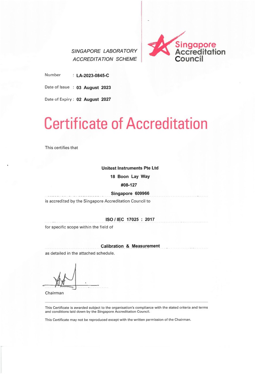
SAC-SINGLAS accredited calibration laboratory (Acc. No. LA-2023-0845-C) serving Singapore's industrial, pharmaceutical, and manufacturing sectors. All content reflects our ISO/IEC 17025 accredited scope and is reviewed by our technical calibration team.
Need 4-20 mA transmitter calibration in Singapore?
Unitest Instruments is SAC-SINGLAS accredited (Acc. No. LA-2023-0845-C) to ISO/IEC 17025. Same-week turnaround, certificates accepted by ISO 9001 and IEC 61511 auditors.