
Key Takeaways
- THD is defined as the ratio of the RMS of all harmonic components to the RMS of the fundamental frequency, expressed as a percentage (THD-F per IEC 61000 standards).
- Singapore's EMA CP5 limits voltage THD to 5% at the point of common coupling (PCC), with individual harmonic limits per IEC 61000-2-2 (e.g. 5th harmonic ≤ 6%, 7th ≤ 5%).
- Non-linear loads (VFDs, switch-mode power supplies, UPS systems, LED drivers), are the primary sources of harmonic injection into commercial and industrial distribution systems.
- Current THD above 20% in three-phase systems can overload neutral conductors to 173% of rated phase current, creating a serious fire and equipment-failure risk.
- Power quality analysers must be calibrated to IEC 61000-4-30 Class A or Class S; uncalibrated instruments may misread THD by 2–5 percentage points, invalidating compliance assessments.
What THD Measures: The Precise Technical Definition
An ideal AC power supply delivers a perfect sinusoidal voltage at a single frequency , 50 Hz in Singapore, 60 Hz in North America. In practice, every conductor in a building carries a mix of the fundamental 50 Hz component and additional frequency components at 100 Hz (2nd harmonic), 150 Hz (3rd harmonic), 250 Hz (5th harmonic), and so on up to the 50th harmonic and beyond. These harmonic voltages and currents are generated by equipment that draws current in pulses rather than as a smooth sine wave, so-called non-linear loads.
Total Harmonic Distortion is the mathematical ratio that quantifies this mixture. The IEC 61000-series definition (referred to as THD-F (referenced to the fundamental)), is:
THD-F (%) = (√(V₂² + V₃² + V₄² + … + Vₙ²) / V₁) × 100
Where V₁ is the RMS voltage of the fundamental component and V₂ through Vₙ are the RMS voltages of each harmonic. A mathematically pure sine wave has 0% THD-F. A square wave (which approximates the output of some old UPS topologies), has a theoretical THD of 48.3%. Real power systems in Singapore commercial buildings typically show voltage THD of 2–5% and current THD of 15–40%, depending heavily on the mix of connected loads.
It is essential to distinguish THD-F from THD-R (referenced to the total RMS value). THD-R always yields a lower numerical result than THD-F for the same waveform. IEC 61000 compliance limits are universally stated in THD-F terms. Instruments set to display THD-R will always appear to report a lower distortion level, which can lead a facilities engineer to incorrectly conclude a site is compliant when it is not.
The Physics of Harmonic Generation
Harmonics arise from the fundamental principle that any periodic, non-sinusoidal waveform can be decomposed into a sum of sinusoidal waves at integer multiples of the fundamental frequency. A consequence of the Fourier theorem. Non-linear loads produce this distortion because their impedance changes with instantaneous voltage: they conduct heavily during the peaks of the AC cycle and barely at all during the mid-cycle troughs, producing a pulsed current waveform rich in harmonic content.
The specific harmonic signature depends on the load topology. A six-pulse rectifier (the most common front-end for variable frequency drives), characteristically injects 5th and 7th harmonics at high amplitude (typically 20–30% of fundamental each), with lower levels of 11th, 13th, and higher-order pairs. A twelve-pulse rectifier cancels 5th and 7th harmonics through phase shifting, producing a much cleaner spectrum dominated by 11th and 13th harmonics. Switch-mode power supplies with single-phase input are dominated by the 3rd harmonic, which in three-phase systems is a triplen harmonic. It does not cancel in the neutral conductor but instead adds arithmetically, a critical safety implication discussed below.
In three-phase balanced systems, even harmonics are theoretically absent due to half-wave symmetry (the positive and negative half-cycles of the waveform are mirror images). In practice, small even-harmonic components appear due to load imbalance and DC offsets. The dominant problem harmonics in Singapore's commercial and industrial facilities are the 3rd, 5th, 7th, and 11th, typically accounting for over 95% of total harmonic power.
Regulatory Limits: IEC 61000 and Singapore's EMA CP5
The international framework for harmonic limits is the IEC 61000 series, published by the International Electrotechnical Commission. The key standards for facilities engineers are:
| Standard | Scope | Key Limits |
|---|---|---|
| IEC 61000-2-2 | Compatibility levels for harmonic voltages in public low-voltage networks | Total voltage THD ≤ 8%; 3rd harmonic ≤ 5%; 5th ≤ 6%; 7th ≤ 5%; 11th ≤ 3.5%; 13th ≤ 3% |
| IEC 61000-3-2 | Harmonic current emission limits for equipment ≤ 16 A/phase | Class A: 3rd harmonic ≤ 2.30 A; 5th ≤ 1.14 A; 7th ≤ 0.77 A; 9th ≤ 0.40 A |
| IEC 61000-3-12 | Harmonic current emission limits for equipment 16–75 A/phase | Limits expressed as ratios (RSCE-dependent); THD(I) typically ≤ 13–16% |
| IEC 61000-4-7 | Measurement technique for harmonics and interharmonics | Specifies 10/12-cycle DFT window, grouping method, Class I and II instrument accuracy |
| IEC 61000-4-30 | Power quality measurement methods | Class A: voltage uncertainty ±0.1%; harmonic uncertainty ±0.5% of nominal; 10-minute aggregation interval |
In Singapore, the Energy Market Authority (EMA) Code of Practice for Electrical Installations (CP5: 2022) is the primary regulatory instrument for connection to the public network. CP5 requires that harmonic voltage distortion at the point of common coupling (PCC) (the boundary between the consumer's installation and SP Group's network), does not exceed the planning levels derived from IEC 61000-3-6. For low-voltage connections, the planning level for total voltage THD is 5%, which is more stringent than the IEC 61000-2-2 compatibility level of 8%. Industrial consumers connecting at 22 kV or 66 kV are subject to even tighter limits and must conduct a harmonic impact assessment before connection.
Need a calibrated power quality assessment in Singapore?
Unitest Instruments calibrates power quality analysers (IEC 61000-4-30 Class A and Class S) and electrical measurement equipment to traceable national standards. SAC-SINGLAS Acc. No. LA-2023-0845-C. Certificates accepted by auditors and regulatory bodies.
How High THD Damages Equipment and Electrical Infrastructure
Transformer Overheating and K-Factor Rating
Transformers are designed and rated for a pure sinusoidal load at the fundamental frequency. Harmonic currents produce additional losses in two forms: eddy current losses in the core and windings, which increase with the square of the frequency; and skin effect losses, which also increase with frequency and force harmonic currents to flow in a smaller cross-section of the conductor, increasing effective resistance. The combined result is that a transformer serving a highly non-linear load operates at a higher internal temperature than its nameplate rating would suggest, shortening insulation life and increasing the risk of catastrophic failure.
The IEEE C57.110 standard introduced the K-factor rating to address this. A transformer with a K-factor rating of 13, for example, is designed to handle a harmonic load mix where the sum of (harmonic number squared × harmonic current squared) equals 13 times the fundamental current squared. Standard transformers have an implicit K-factor of 1. Fitting a standard transformer where a K-13 transformer is required is a common and dangerous design error in Singapore data centres and office buildings with high VFD or UPS density.
Neutral Conductor Overloading
In a balanced three-phase system, the fundamental-frequency currents in the three phase conductors sum to zero in the neutral, which is why older three-phase installations were designed with a neutral conductor rated at 50% or less of the phase conductor cross-section. Triplen harmonics (3rd, 9th, 15th, 21st) are a special case: because they are in phase in all three conductors, they do not cancel but add arithmetically. In a building where every circuit feeds switch-mode power supplies with 80% third-harmonic current content, the neutral can carry up to 173% of the phase current. An undersized neutral conductor in this scenario is a serious fire hazard and the direct cause of multiple electrical fires in Singapore commercial buildings in recent years.
Capacitor Bank Resonance
Power factor correction capacitor banks, commonly installed in Singapore industrial facilities to avoid EMA reactive power charges, present a very low impedance to harmonic frequencies. The combination of the capacitor bank's capacitive reactance and the system's inductive reactance (from transformers and cables) forms a parallel resonant circuit. If the resonant frequency coincides with a dominant harmonic (most commonly the 5th or 7th), the result is a resonant amplification of that harmonic voltage, potentially to levels five to ten times the normal harmonic voltage. This causes capacitor failure, nuisance tripping of protection relays, and disturbance to voltage-sensitive process equipment.
Measurement Methods and Instrumentation Requirements
Accurate THD measurement requires instruments designed and calibrated specifically for harmonic analysis. IEC 61000-4-7 specifies the measurement algorithm: a Discrete Fourier Transform (DFT) applied to exactly 10 complete cycles of 50 Hz (200 ms window), synchronised to the fundamental using a phase-locked loop. The resulting spectral lines are then grouped according to the IEC 61000-4-7 grouping method into harmonic groups. This methodology is implemented in IEC 61000-4-30 Class A power quality analysers.
IEC 61000-4-30 defines two instrument classes. Class A instruments (examples: Fluke 435-II, Hioki PW3198, Dranetz HDPQ) have the tightest uncertainty requirements (voltage RMS uncertainty of ±0.1% of declared input voltage, harmonic voltage uncertainty of ±0.5% of nominal input), and are required for compliance testing, contractual measurements, and assessments used in regulatory submissions. Class S instruments have relaxed requirements and are suitable for surveys and energy audits where the uncertainty budget is less critical.
A critical but frequently overlooked requirement is that the current measurement accuracy depends entirely on the current transformers (CTs) used with the analyser. Flexible Rogowski coil CTs have different frequency response characteristics than rigid split-core CTs, and neither should be used beyond the frequency range stated in their calibration certificate. In practice, the CT is frequently the dominant uncertainty contributor in a harmonic measurement, particularly at higher harmonic orders (11th and above).
As we explain in detail in our guide to measurement uncertainty in calibration, every component in the measurement chain (the analyser, the CTs, and the voltage input leads), contributes to the combined measurement uncertainty that must be reported alongside any compliance measurement. For regulatory submissions to EMA, the expanded uncertainty (at k=2, 95% confidence) must be declared.
Calibration Requirements for Power Quality Instruments
Power quality analysers are precision electronic instruments containing voltage dividers, analogue-to-digital converters, and digital signal processors that drift over time. Temperature cycling, mechanical vibration during transport, and component ageing all contribute to drift in the instrument's amplitude and phase accuracy. Both of which directly affect THD measurement accuracy.
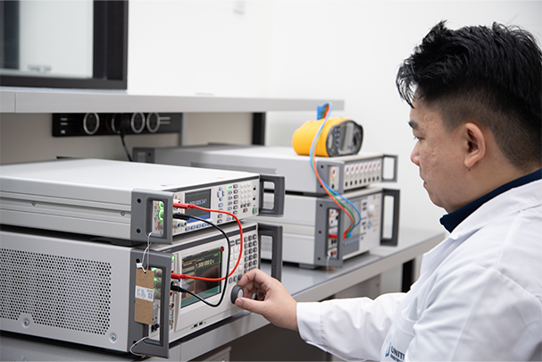
Calibration of a power quality analyser verifies that the instrument's measurement of harmonic amplitudes and phase angles meets the IEC 61000-4-30 Class A or Class S specification across all frequencies up to at least the 50th harmonic (2500 Hz). This requires a specialist calibration source capable of generating stable, low-distortion multi-tone signals with precisely known harmonic content. A capability that is fundamentally different from the single-frequency sine wave sources used for basic voltage calibration.
The concept of accredited versus non-accredited calibration is particularly important for power quality instruments used in compliance testing. An accredited calibration certificate issued by a SAC-SINGLAS laboratory demonstrates that the calibration was performed using equipment traceable to national measurement standards, by competent personnel, following documented procedures with a defined measurement uncertainty budget, all requirements of ISO/IEC 17025. A non-accredited "calibration" sticker from an unaccredited service provider provides none of these assurances and is not accepted by EMA or ISO 9001 auditors as evidence of instrument fitness for compliance measurement.
Most instrument manufacturers recommend annual calibration intervals for power quality analysers used in active compliance monitoring. IEC 62446-3 (power quality in photovoltaic systems) and internal quality management systems may specify shorter intervals (typically six months), for instruments used in continuous field service where mechanical stress accelerates drift. Understanding how to determine the correct calibration interval for your specific instruments and usage conditions is an important part of a facility's measurement assurance programme.
Common Mistakes Facilities Engineers Make with THD
Even experienced facilities engineers make a consistent set of errors when assessing and managing power quality. The most consequential are the following.
Measuring at the wrong point in the system
THD varies significantly across the distribution system. Voltage THD at the main low-voltage switchboard may be 3%, while the same site may show 8% voltage THD at a sub-distribution board feeding a cluster of VFDs. Well above the IEC compatibility level. Compliance with EMA's PCC limit does not mean individual loads and sub-systems are operating within safe distortion levels. A comprehensive power quality survey measures at multiple points: PCC, main distribution board, motor control centres, and critical loads.
Confusing voltage THD and current THD
Voltage THD and current THD are related but distinct quantities. A site can have acceptable voltage THD (below 5%) but very high current THD (above 40%) at the load terminals. High current THD is the cause of the damage mechanisms described above (transformer heating, neutral overloading, and resonance), even when voltage THD appears acceptable. Both quantities must be measured, and current THD requires accurate CTs calibrated across the relevant harmonic range.
Using an uncalibrated or inadequate instrument
A standard digital multimeter measures RMS voltage correctly for a pure sine wave, but most multimeters use an average-responding rectifier with RMS-calibrated scaling. A method that is accurate only for sine waves. When measuring a distorted waveform, an average-responding multimeter will under-read the true RMS by an amount that depends on the harmonic content. Only true-RMS instruments with sufficient bandwidth (at least 2.5 kHz for 50th harmonic measurement) are suitable. And as noted above, even true-RMS instruments must be calibrated to IEC 61000-4-30 to produce defensible compliance results.
Ignoring interharmonics and supraharmonics
IEC 61000-4-7 also covers interharmonic components (frequencies between the integer harmonic orders), and the 2009 edition introduced the concept of supraharmonics (2–150 kHz), increasingly important as variable speed drives with high switching frequencies proliferate. Modern LED lighting drivers, EV chargers, and photovoltaic inverters are significant sources of supraharmonic disturbance. These components are not captured by instruments limited to integer harmonic measurement and require broadband power quality analysers with extended frequency range.
Frequently Asked Questions
Total Harmonic Distortion (THD) is a ratio that expresses how much of an AC voltage or current waveform consists of harmonic frequencies. Integer multiples of the fundamental (50 Hz in Singapore). It is calculated as the square root of the sum of the squares of all harmonic amplitudes divided by the amplitude of the fundamental, expressed as a percentage. A pure sine wave has 0% THD. Practical power systems typically exhibit voltage THD of 2–5% and current THD of 10–40% depending on connected loads.
IEC 61000-3-2 sets harmonic current emission limits for equipment with input current up to 16 A per phase. Class A equipment must not exceed defined per-harmonic limits, for example, the 3rd harmonic must not exceed 2.30 A and the 5th must not exceed 1.14 A. IEC 61000-2-2 sets voltage harmonic compatibility levels for public low-voltage networks, with a total voltage THD limit of 8% and individual harmonic limits (e.g. 5th harmonic ≤ 6%, 7th ≤ 5%). IEC 61000-4-7 and IEC 61000-4-30 specify the measurement methods and instrumentation accuracy classes for these assessments.
Singapore's Energy Market Authority (EMA) Code of Practice for Electrical Installations (CP5) references IEC 61000 series limits and requires that harmonic distortion at the point of common coupling (PCC) does not exceed agreed voltage quality levels. Voltage THD at the PCC for low-voltage networks should not exceed 5% total. More stringent than the IEC 61000-2-2 compatibility level of 8%. Individual harmonic voltage limits are aligned to IEC 61000-3-6 planning levels (e.g. 3rd harmonic ≤ 4%, 5th ≤ 5%). Large industrial consumers connecting to the medium-voltage network are subject to additional harmonic assessment under the Singapore Electricity Grid Code.
High THD is predominantly caused by non-linear loads. Equipment whose impedance varies with the instantaneous voltage, drawing current in pulses rather than as a smooth sine wave. Common sources include variable frequency drives (VFDs) for HVAC and pump systems, which inject 5th and 7th harmonics at levels of 25–40% THD(I); switch-mode power supplies in computers and data centres (3rd harmonic dominant); LED drivers and electronic ballasts; UPS systems in double-conversion mode; arc welding equipment; and battery chargers. In Singapore's dense commercial buildings, the aggregation of thousands of switch-mode power supplies often drives total current THD above 30% at the distribution board.
Power quality analysers compliant with IEC 61000-4-30 Class A or Class S are the standard instruments. Class A instruments (e.g. Fluke 435-II, Hioki PW3198) have uncertainty requirements of ±0.1% for voltage RMS and ±0.5% for individual harmonics up to the 50th order. Class S instruments have relaxed uncertainty budgets and are suitable for survey measurement. All power quality instruments used for compliance assessment should be calibrated to IEC 61000-4-30 and IEC 61000-4-7. Calibration must be traceable to national measurement standards, such as those maintained by Singapore's National Metrology Centre (NMC).
High THD causes measurable physical damage through three primary mechanisms. First, I²R heating: harmonic currents increase core and winding losses in transformers. A 20% current THD load can cause up to 10% additional losses compared to a purely sinusoidal load. Second, neutral conductor overloading: triplen harmonics (3rd, 9th, 15th) do not cancel in the neutral of three-phase systems and can drive neutral current to 173% of phase current, causing overheating and fire risk. Third, capacitor resonance: harmonic frequencies can resonate with power factor correction capacitors, causing overvoltages that exceed insulation ratings and cause capacitor failure.
Power quality analysers contain precision voltage dividers, current transformers, and analogue-to-digital converters that drift over time due to component ageing, temperature cycling, and mechanical stress. An uncalibrated analyser may under-read THD by 2–5 percentage points. Sufficient to misclassify a non-compliant site as compliant. Most manufacturers and accredited laboratories recommend an annual calibration interval for instruments used in compliance testing. Instruments in continuous field service may require six-monthly calibration. Calibration must be performed by a SAC-SINGLAS accredited laboratory to produce certificates accepted by EMA and ISO 9001 auditors.
THD-F (referenced to the fundamental) expresses total harmonic content as a percentage of the fundamental frequency component. The definition used in all IEC 61000 standards. THD-R (referenced to the total RMS value) expresses the same harmonic content as a percentage of the total RMS value. THD-R always gives a lower number than THD-F for the same waveform. For example, a 30 A harmonic on a 100 A fundamental gives THD-F = 30% but THD-R = 28.7%. Always confirm which definition your instrument uses before comparing against IEC 61000 limits, which are all in THD-F terms. Using THD-R will make a non-compliant site appear compliant.
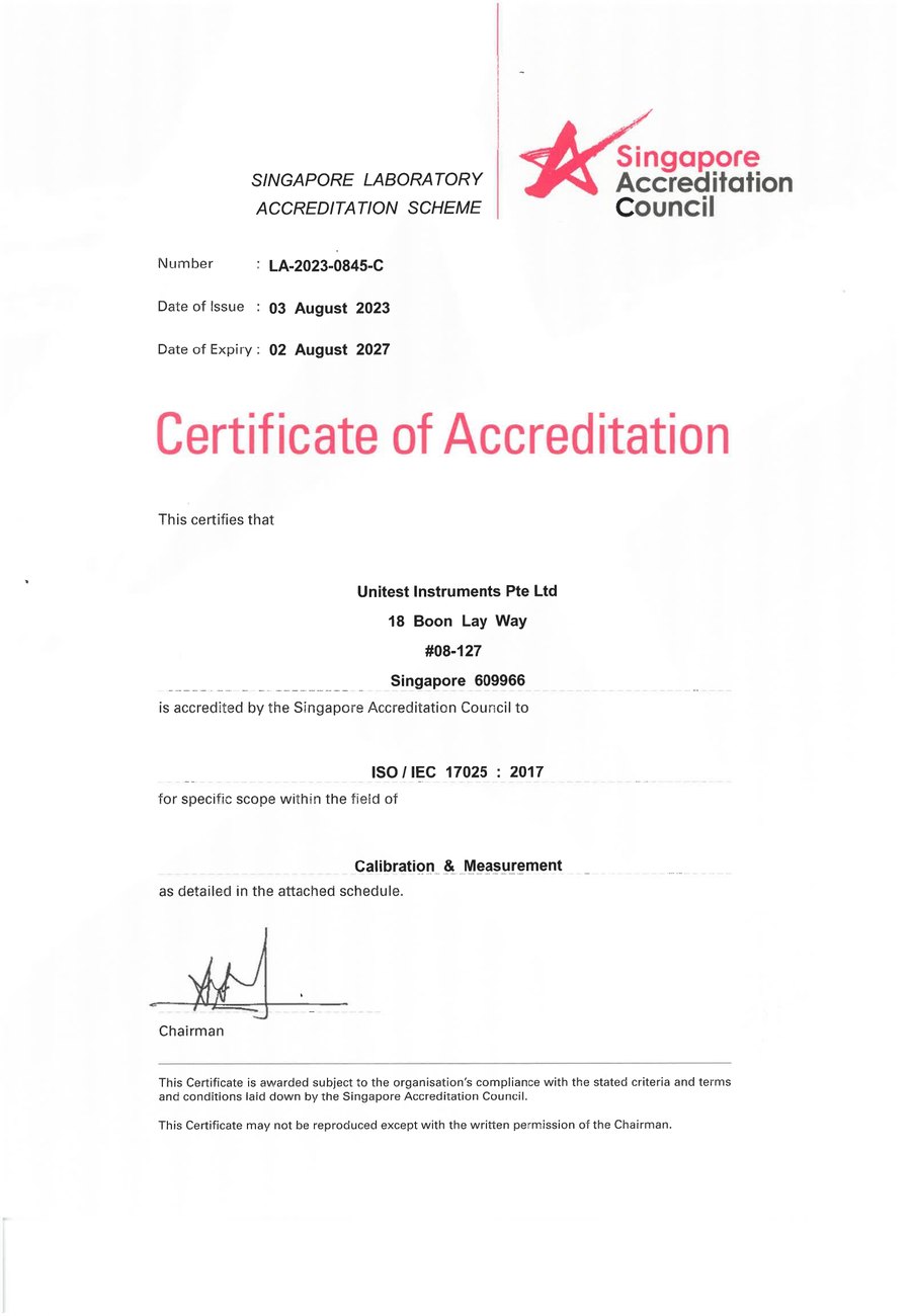
SAC-SINGLAS accredited calibration laboratory (Acc. No. LA-2023-0845-C) serving Singapore's industrial, pharmaceutical, and manufacturing sectors. All content reflects our ISO/IEC 17025 accredited scope and is reviewed by our technical calibration team.
Need electrical and power quality calibration in Singapore?
Unitest Instruments is SAC-SINGLAS accredited (Acc. No. LA-2023-0845-C) to ISO/IEC 17025. We calibrate power quality analysers, clamp meters, insulation testers, and electrical measurement equipment. Same-week turnaround, certificates accepted by ISO 9001 auditors and EMA compliance assessments.