
Key Takeaways
- A 24-bit ADC achieves approximately 0.6 µV resolution on a 10 V range, but effective noise-free resolution is always lower than the nominal bit count due to input noise and non-linearity.
- NPLC must be configured to match Singapore's 50 Hz mains frequency. Using a 60 Hz setting (the US default) degrades Normal Mode Rejection by 20–40 dB and is a common misconfiguration error.
- CMRR is frequency-dependent: a system specified at 80 dB DC CMRR may deliver only 50–60 dB at 50 Hz. Always check the frequency-referenced CMRR figure, not just the DC specification.
- Both CMRR degradation and finite resolution must be included as Type B uncertainty contributions in ISO/IEC 17025 measurement uncertainty budgets (JCGM 100:2008 / GUM framework).
- Guard-driven or isolated differential inputs dramatically improve CMRR in high-impedance or long-lead measurement scenarios common in Singapore's industrial and cleanroom environments.
What Is CMRR? Defining Common Mode Rejection Ratio
Common Mode Rejection Ratio (CMRR) is a figure of merit for differential measurement inputs. It quantifies the ability of the input stage to amplify the differential signal (the voltage difference between the positive (HI) and negative (LO) terminals), while simultaneously rejecting the common mode signal, which is any voltage that appears identically on both terminals with respect to the instrument's chassis ground.
Mathematically, CMRR is defined as:
CMRR (dB) = 20 × log₁₀ (Differential Gain / Common Mode Gain)
A CMRR of 80 dB means the instrument attenuates common mode signals by a factor of 10,000 relative to the differential signal. At 100 dB, the rejection factor reaches 100,000. At 120 dB (achievable by high-end precision DAQ front-ends and six-and-a-half-digit DMMs), common mode signals are suppressed by one million to one. In practical terms, a 1 V common mode interference at 120 dB CMRR appears as only 1 µV of added error on the differential reading.
Where Common Mode Noise Comes From
Common mode noise enters measurement circuits through several physical mechanisms. The most ubiquitous in Singapore's industrial environment is ground potential difference: when the instrument chassis ground and the measurement source ground are connected to different points on the facility's earthing system, a voltage difference (often tens of millivolts at 50 Hz) appears as a common mode signal. A second source is electrostatic coupling from adjacent power cables, particularly in cable trays shared between signal and power wiring. A third source is thermoelectric EMF at connector junctions, which can appear as DC common mode offset in precision DC measurements. In all three cases, high CMRR is the first line of defence.
ADC Resolution: Nominal Bits Versus Effective Resolution
The analogue-to-digital converter (ADC) at the heart of any DAQ system converts continuous analogue voltages into discrete digital numbers. Resolution is commonly stated as the number of bits in the conversion: a 16-bit ADC produces output codes from 0 to 65,535 (2¹⁶ − 1), giving 65,536 discrete levels. On a ±10 V full-scale range, the ideal resolution per least-significant bit (LSB) is:
Resolution = Full-Scale Range / 2^N = 20 V / 65,536 ≈ 305 µV per bit
For a 24-bit ADC on the same range: 20 V / 16,777,216 ≈ 1.19 µV per bit. These are theoretical ideals. In practice, noise-free resolution (the number of stable, non-flickering digits in the reading), is always lower. Input-referred noise from the amplifier front-end, aperture jitter in the sampling clock, and integral non-linearity (INL) of the ADC all erode the effective bit count. A well-designed 24-bit DAQ system typically achieves 20–21 noise-free bits at low bandwidth; a mediocre design may achieve only 16–17 effective bits from the same silicon.
Manufacturers express this in different ways. Bench DMMs specify reading resolution in terms of "digits" or "counts" (e.g. "6½ digits" = 1,200,000 counts on the top range). DAQ modules often specify "noise-free bits" or "effective number of bits" (ENOB). The ENOB is the figure to use in measurement uncertainty budgets, not the nominal ADC bit depth. Blindly using nominal bit depth in uncertainty calculations is a systematic error that overstates instrument capability.
| ADC Type | Nominal Bits | Typical ENOB (Low BW) | Ideal LSB on ±10 V | Typical Noise Floor |
|---|---|---|---|---|
| SAR ADC (fast) | 16-bit | 14–15 bits | 305 µV | ~1–5 mV rms |
| Delta-Sigma ADC (precision) | 24-bit | 20–21 bits | 1.19 µV | ~2–10 µV rms |
| Integrating ADC (bench DMM) | 22–28 bit equiv. | 18–22 bits | <0.1 µV | <1 µV rms (1 NPLC) |
| Flash ADC (high-speed) | 8–12 bit | 7–10 bits | 78 mV (8-bit) | >10 mV rms |
NPLC: Integration Time and Mains Noise Rejection
Integrating ADCs (used in bench DMMs and precision DAQ front-ends), do not sample the input instantaneously. Instead they integrate (average) the input signal over a defined time window. The duration of this window is set by the NPLC parameter: Number of Power Line Cycles. At Singapore's 50 Hz mains frequency, one power line cycle = 20 ms. Therefore:
- 0.02 NPLC = 0.4 ms integration, fast but noisy
- 0.1 NPLC = 2 ms integration. Moderate speed, moderate noise
- 1 NPLC = 20 ms integration. One full 50 Hz cycle cancelled
- 10 NPLC = 200 ms integration , 10 cycles cancelled, very low noise
- 100 NPLC = 2,000 ms integration. Maximum noise rejection, slowest throughput
When the integration window is exactly an integer multiple of the mains cycle, the average of the sinusoidal interference over the window equals zero, the noise cancels algebraically. This is the principle behind Normal Mode Rejection (NMR). At 1 NPLC with a correctly set line frequency, Normal Mode Rejection of 50 Hz noise typically exceeds 60 dB (a factor of 1,000 reduction in the noise amplitude contribution to the reading). At 10 NPLC, NMRR can exceed 80 dB.
Speed vs. Accuracy Trade-off
The fundamental trade-off with NPLC is speed versus accuracy. At 100 NPLC (2 seconds per reading at 50 Hz), a 6½-digit DMM can achieve noise floors below 100 nV on a 100 mV range. Suitable for thermocouple calibration and resistance bridge measurements. At 0.02 NPLC (25,000 readings per second), the same instrument may be 100–1,000× noisier. For calibration certificate generation where each reference point must meet a stated uncertainty, the NPLC must be set high enough that the reading noise contribution is negligible compared to the dominant uncertainty sources (reference standard, thermal EMF, etc.).
Need your DAQ system or DMM calibrated in Singapore?
Unitest Instruments performs traceable calibration of data acquisition systems, bench DMMs, and precision voltage sources, accredited under SAC-SINGLAS LA-2023-0845-C. Same-week turnaround available.
How CMRR, Resolution, and NPLC Interact
These three parameters are not independent. They interact in ways that determine the overall system accuracy floor. Consider a practical scenario: measuring a 10 mV DC thermocouple signal in an industrial plant in Singapore, where a 1 V, 50 Hz common mode noise voltage is present on both signal leads, and 5 mV of 50 Hz ripple rides on the signal itself.
With a CMRR of 80 dB at 50 Hz, the 1 V common mode signal contributes 1 V / 10,000 = 100 µV of error to the reading. If the target measurement uncertainty is 50 µV, this alone exceeds budget. Raising CMRR to 100 dB reduces the contribution to 10 µV, within budget. Simultaneously, setting 1 NPLC rejects the 5 mV, 50 Hz series-mode ripple to below 5 µV. And choosing a 24-bit delta-sigma ADC with a 1 µV noise floor means the resolution contribution (half-LSB / √3 ≈ 0.35 µV) is negligible. All three parameters must be adequate simultaneously. A weak link in any one can dominate the error budget and invalidate the other two improvements.
Guard Terminals and Driven Guards
High-CMRR performance depends critically on the input circuit topology. A simple differential input with a common reference ground loses CMRR rapidly as source impedance increases, because any impedance imbalance between the HI and LO paths converts common mode voltage into differential-mode error. The solution in precision DAQ design is the driven guard (also called guard terminal or shield drive). The guard is a third terminal driven to the common mode voltage by a low-impedance amplifier buffer, surrounding the signal leads and eliminating the capacitive leakage path that degrades CMRR at high frequencies. Instruments with guard terminals can maintain CMRR above 100 dB even at kHz frequencies, which is essential for fast DAQ applications in Singapore's electrically noisy manufacturing environments.
Calibration Implications and ISO/IEC 17025 Requirements
Under ISO/IEC 17025 (the international standard adopted by Singapore's SAC-SINGLAS accreditation body), laboratories must evaluate and report the measurement uncertainty of every result. For DAQ-based measurements, this requires explicitly accounting for the contributions of CMRR limitations, finite resolution, and NPLC-related noise rejection in the uncertainty budget.
The JCGM 100:2008 Guide to the Expression of Uncertainty in Measurement (GUM) classifies uncertainty sources as Type A (evaluated by statistical methods, e.g. repeated readings) and Type B (evaluated by other means, e.g. manufacturer specifications, physics, prior data). CMRR and resolution are Type B contributions:
- Resolution contribution: modelled as a rectangular probability distribution with half-width = ½ × LSB (or ½ × last displayed digit). Standard uncertainty = (½ × LSB) / √3.
- CMRR contribution: the worst-case common mode voltage present during measurement, divided by the CMRR ratio (not dB), gives the maximum error from this source. This is typically modelled as a rectangular distribution, giving standard uncertainty = (V_cm / CMRR_ratio) / √3.
Both are then combined in quadrature with other contributors (reference standard uncertainty, thermal EMF, repeatability, self-heating, cable resistance) to yield the combined standard uncertainty, which is multiplied by a coverage factor (typically k=2 for 95% confidence) to give the expanded uncertainty reported on the calibration certificate.
A failure mode observed during SAC-SINGLAS technical assessments is laboratories that correctly characterise their reference standard uncertainty but neglect to include DAQ system contributions. Particularly CMRR degradation at 50 Hz. This systematically understates measurement uncertainty and can result in non-conformant calibration certificates. As noted in our article on measurement uncertainty, every significant contributor must be included and justified in the uncertainty budget.
Practical Configuration and Common Mistakes
Even a high-specification DAQ system will underperform if configured incorrectly. The following are the most frequently encountered errors in Singapore calibration laboratories and industrial instrumentation installations:
1. Wrong Line Frequency Setting
As discussed above, defaulting to 60 Hz on a 50 Hz grid destroys NMRR. This is the single most common source of unexpected noise on precision measurements in Singapore. The fix is a single menu setting. Check it first before investigating hardware faults.
2. Using Nominal ADC Bits in Uncertainty Calculations
Stating resolution as "24-bit = 1.19 µV" when the effective noise floor is 10 µV understates the resolution uncertainty contribution by nearly an order of magnitude. Always use the manufacturer's specified noise-free counts or ENOB figure, and verify it with your own noise floor measurement at the intended NPLC setting and input configuration.
3. Ignoring CMRR Frequency Dependence
DAQ specifications typically quote DC CMRR (e.g. 120 dB). The 50 Hz CMRR may be 20–40 dB lower. The relevant figure for Singapore's industrial applications is always the CMRR at the frequencies present in the measurement environment. Primarily 50 Hz and its harmonics (100 Hz, 150 Hz, 200 Hz).
4. Floating Inputs Without Guard Connection
Leaving inputs floating (unconnected to a defined common mode reference) or failing to connect the guard terminal causes unpredictable common mode behaviour. In multi-channel DAQ systems scanning multiple signals from different source impedances, always define the common mode reference and use the guard terminal where provided.
5. Mixing Signal and Power Wiring
Running sensor signal cables in the same conduit or tray as 230 V power cables (Singapore's standard mains voltage) induces common mode voltages that challenge even high-CMRR inputs. Physically separating signal and power wiring (or using shielded twisted-pair cables with the shield connected at a single point), reduces the common mode voltage presented to the input and reduces the CMRR demand on the instrument.
| Configuration Error | Effect on Accuracy | Typical Magnitude | Fix |
|---|---|---|---|
| 60 Hz NPLC on 50 Hz grid | Loss of NMRR at 50 Hz | −20 to −40 dB rejection | Set line frequency to 50 Hz |
| Nominal bits used as resolution | Understated uncertainty budget | 2–10× understatement | Use ENOB or noise-free counts |
| DC CMRR assumed at 50 Hz | Understated CMRR error contribution | 20–40 dB optimism | Use 50 Hz CMRR from datasheet |
| Guard terminal unconnected | Degraded CMRR, especially at high impedance | Up to 40 dB CMRR loss | Connect guard to source shield/ground |
| NPLC too low for precision DC | Excessive noise on reading | 10–100× worse noise floor | Increase NPLC to 1, 10, or 100 |
Singapore Regulatory Context and Standards
In Singapore, the primary framework governing measurement accuracy in accredited laboratories is ISO/IEC 17025:2017, administered by the Singapore Accreditation Council (SAC) through its SINGLAS programme (SAC-SINGLAS). All calibration certificates issued by SAC-SINGLAS accredited laboratories (including Unitest Instruments (Acc. No. LA-2023-0845-C)), must carry measurement uncertainty stated in accordance with JCGM 100:2008. The National Metrology Centre (NMC) at A*STAR provides Singapore's primary measurement standards, and traceability chains from NMC through accredited laboratories to working instruments must be unbroken and documented. As detailed in our article on measurement traceability, this chain ensures that a voltage reading made on a production line in Jurong or a cleanroom in Woodlands is ultimately referenced to Singapore's national realisation of the SI volt.
For data acquisition systems specifically, relevant international standards include IEC 61010-1 (safety for electrical measurement equipment), IEC 60770 (transmitter performance), and for high-accuracy DC voltage measurement, the BIPM's key comparison database (CCEM-K11) which links national voltage standards globally. Singapore's NMC participates in relevant BIPM key comparisons, providing the metrological foundation for CMRR, resolution, and linearity characterisation of reference instruments used in SAC-SINGLAS accredited calibrations.
Frequently Asked Questions
CMRR, or Common Mode Rejection Ratio, is the ability of a differential amplifier or measurement input to reject voltage signals that appear equally on both the positive and negative input terminals (common mode signals) while amplifying the differential signal between them. In data acquisition, CMRR matters because real-world measurement environments are full of common mode noise , 50 Hz mains interference, ground potential differences, and electrostatic coupling. A high CMRR (typically expressed in dB) means the DAQ system can see the small signal you care about without being overwhelmed by noise that is common to both inputs. A CMRR of 80 dB means common mode signals are rejected by a factor of 10,000; at 120 dB, the rejection is one million to one.
NPLC stands for Number of Power Line Cycles. It refers to the integration time of the analogue-to-digital converter expressed as a multiple of the local power line frequency period (20 ms at 50 Hz in Singapore; 16.67 ms at 60 Hz in the USA). Setting NPLC to 1 means the ADC integrates for one full mains cycle (20 ms in Singapore), which causes the converter to average out exactly one full cycle of 50 Hz noise, dramatically reducing mains-frequency interference. Higher NPLC settings (10 or 100) give even better noise rejection at the cost of slower readings. Lower settings (0.02 or 0.1 NPLC) give fast readings but with more noise and lower effective resolution.
ADC resolution determines the smallest voltage step the converter can distinguish. A 16-bit ADC divides its full-scale range into 2^16 = 65,536 discrete levels; a 24-bit ADC provides 16,777,216 levels. On a 10 V range, a 16-bit ADC has a theoretical resolution of about 153 µV per bit, while a 24-bit ADC reaches approximately 0.6 µV per bit. However, effective resolution (also called noise-free resolution), is always lower than the nominal bit count due to input noise, aperture jitter, and non-linearity. Manufacturers typically specify "counts" or "digits" to reflect the effective reading resolution after noise is considered, which is the figure that matters for calibration and measurement uncertainty calculations.
There is no single statutory CMRR requirement for DAQ systems in Singapore, but the relevant benchmarks are set by the instrument standards and accreditation requirements that apply to the application. For general-purpose precision measurement, IEC 61010-1 covers safety, while instrument accuracy classes under IEC 60359 and the calibration requirements of ISO/IEC 17025 (adopted by SAC-SINGLAS in Singapore) define traceability and uncertainty requirements. In practice, laboratory-grade DAQ inputs typically require CMRR of at least 80 dB at DC and 60 dB at 50/60 Hz to achieve the noise floors necessary for 0.01% or better accuracy. Industrial-grade systems often specify CMRR of 100–120 dB for compliance with sensitive process measurement.
Normal Mode Rejection Ratio (NMRR) and Common Mode Rejection Ratio (CMRR) address different noise paths. CMRR measures how well the differential input rejects signals that appear identically on both input terminals relative to instrument ground, for example, a 50 Hz interference voltage picked up by both signal leads. NMRR (sometimes called Series Mode Rejection) measures how well the measurement rejects noise that appears in series with the signal, i.e. between the two input terminals. Such as ripple superimposed directly on a DC signal. NPLC integration primarily improves NMRR by averaging over complete mains cycles. Both ratios must be adequate for accurate measurements in electrically noisy environments.
Under ISO/IEC 17025 and the JCGM 100:2008 (GUM) framework used by SAC-SINGLAS accredited laboratories, CMRR limitations and finite resolution must both be evaluated as Type B uncertainty contributions. CMRR degradation at frequency is typically modelled as a systematic uncertainty component based on the worst-case common mode voltage present during measurement. Resolution contributes a rectangular distribution with half-width equal to half the least significant digit, giving a standard uncertainty of (resolution/2)/√3. Both components are combined in quadrature with other sources such as reference standard uncertainty, thermal EMF, and repeatability. Failing to include CMRR and resolution components is a common finding during SAC-SINGLAS technical assessments.
Yes. This is critical and frequently misconfigured. Singapore's national grid operates at 50 Hz (period = 20 ms). NPLC settings must be programmed relative to 50 Hz to achieve maximum Normal Mode Rejection. Many DAQ systems and bench DMMs default to 60 Hz (the US standard, period = 16.67 ms). If a 60 Hz NPLC setting is used in Singapore, the integration window does not align with the actual mains cycle and mains-frequency noise is not cancelled effectively, degrading NMRR by 20–40 dB. Always confirm the power line frequency setting in your instrument's configuration menu before deploying in Singapore, Malaysia, or any 50 Hz territory.
Calibration interval depends on the instrument's specified drift rate, the measurement uncertainty required, and the risk profile of the application. Most precision DAQ instruments and bench DMMs are calibrated annually as a starting point, but ISO/IEC 17025 requires laboratories to justify intervals based on historical data. High-resolution DAQ front-ends used in primary standards applications may require 6-monthly calibration. Lower-accuracy monitoring systems used in non-critical industrial processes may tolerate 2-year intervals if drift data supports it. SAC-SINGLAS guidance and ILAC P10 both emphasise that calibration intervals must be reviewed and documented. A fixed 12-month interval without evidence is insufficient for a compliant metrology programme.
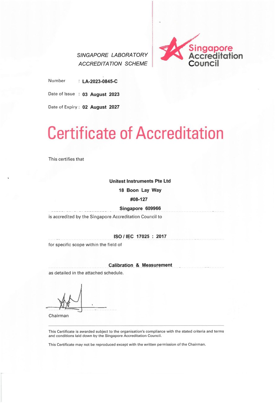
SAC-SINGLAS accredited calibration laboratory (Acc. No. LA-2023-0845-C) serving Singapore's industrial, pharmaceutical, and manufacturing sectors. All content reflects our ISO/IEC 17025 accredited scope and is reviewed by our technical calibration team.
Need data acquisition or DMM calibration in Singapore?
Unitest Instruments is SAC-SINGLAS accredited (Acc. No. LA-2023-0845-C) to ISO/IEC 17025. Same-week turnaround, certificates accepted by ISO 9001 auditors.