
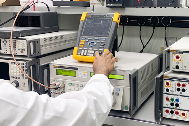
Key takeaways
- Four key parameters are verified in oscilloscope calibration: DC accuracy (voltage), timebase accuracy (time), bandwidth (frequency response), and triggering (minimum detectable edge or pulse).
- Bandwidth specification is the most commonly misunderstood: a 500MHz oscilloscope has -3dB response at 500MHz. Meaning at 500MHz it reads 30% lower amplitude than at DC. The true usable bandwidth for accurate measurements is typically 1/3 of the specified bandwidth.
- Probes must be calibrated alongside the oscilloscope. A correctly calibrated oscilloscope with a de-calibrated probe gives incorrect readings. Probe calibration includes bandwidth, attenuation ratio, and input impedance.
- Digital oscilloscopes (DSOs) and mixed-signal oscilloscopes (MSOs) require the same fundamental calibration as analog scopes; sampled-data effects add additional considerations for high-speed signals.
- For compliance testing in Singapore (EMC, power quality, communications standards), oscilloscope calibration certificates are part of the test equipment evidence required by labs seeking ILAC-MRA accredited test reports.
Oscilloscope calibration parameters at a glance
The table below summarises the eight parameters verified during a full oscilloscope calibration, what each test is checking, the typical specification range, and the calibration tool required to perform the verification.
| Parameter | What is verified | Typical specification | Calibration tool |
|---|---|---|---|
| DC accuracy | Vertical amplifier gain at each sensitivity setting | ±1.5% to ±3% of full scale | Precision DC voltage calibrator |
| DC offset | Zero offset at each vertical position | ±(1% + 2mV) typical | Same as above |
| Timebase accuracy | Time/division accuracy across ranges | ±(15–50) ppm | Frequency reference (GPS-locked or Cs standard) |
| Bandwidth | -3dB frequency response of vertical amplifier | Per scope specification (e.g. 500MHz) | RF signal generator + power splitter |
| Rise time | Measured rise time of known fast step | Related to bandwidth: tr ≈ 0.35/BW | Pulse generator |
| Input impedance | 1MΩ and 50Ω input impedances | ±2% (1MΩ), ±1% (50Ω) | Precision LCR meter or network analyser |
| Trigger sensitivity | Minimum signal for stable triggering | Per spec (e.g. 1 div at BW) | Signal generator |
| Probe attenuation | 10:1 probe calibration check | ±2% at each frequency | Same sources as above |
Why oscilloscope measurements can be wrong
The oscilloscope is often assumed to be a transparent window onto a signal. A device that simply displays what is happening at the probe tip. In reality it is a measurement instrument with accuracy specifications, drift characteristics, and uncertainty budgets just like any other instrument in a calibrated laboratory.
A scope that reads a 5V signal as 5.2V will give systematically incorrect amplitude measurements across all its sensitivity ranges. A scope with a timebase error of 0.1% will give systematically incorrect frequency and period measurements. Every timing measurement is offset by that factor. For a single measurement in isolation, those errors may be acceptable. But in a multi-instrument measurement chain (as found in electronics manufacturing, R&D labs, and compliance test environments), the cumulative effect of multiple instruments with unchecked accuracy can make test results genuinely unreliable.
Singapore's electronics ecosystem spans semiconductor packaging, consumer electronics, precision instruments, medical devices, and aerospace maintenance. In each of these sectors, oscilloscopes are used not just for fault-finding but for production go/no-go decisions, design verification, and compliance test evidence. In that context, an oscilloscope that has not been calibrated in three years (with unknown DC accuracy and potentially degraded bandwidth), is not a measurement instrument: it is a display device.
Calibration converts the oscilloscope back into an instrument with a known, documented, and traceable relationship between its displayed values and the physical signal at the probe tip. The calibration certificate is the evidence of that relationship, together with its limits. The stated measurement uncertainty that tells you how much confidence to place in the result.
The four calibration parameters in detail
DC accuracy. The vertical amplifier
The vertical amplifier must scale correctly at every sensitivity setting, from 1mV/div through to 5V/div. Accuracy degrades over time due to aging of the resistors and capacitors in the amplifier gain network. These components drift gradually. A predictable, slow process that means a scope that was within specification when delivered may no longer be within specification three years later without adjustment.
A 1% DC accuracy error on the 200mV/div range means the oscilloscope reads a 200mV signal as 202mV. On a 5V/div range with a 2% specification, a 10V signal could be displayed as 10.2V. These errors are small in isolation. In a production test that requires a signal to be within ±3% of a nominal value, an uncalibrated scope with a 2% gain error consumes two-thirds of the entire measurement allowance. Before any other uncertainty source is considered.
Timebase accuracy. The horizontal reference
The time base oscillator (typically a temperature-compensated crystal oscillator (TCXO) or oven-controlled crystal oscillator (OCXO)), determines horizontal accuracy. Crystal oscillator aging is a well-understood phenomenon: frequency drifts from the nominal value at a rate of approximately 1ppm per year for a TCXO, and significantly less for an OCXO. But even 1ppm per year accumulates: after five years without calibration, a TCXO-based timebase could have drifted 5ppm from its nominal value.
A 50ppm timebase error means that frequency measurements are wrong by 50Hz per MHz. A 10MHz signal would be measured as 10.0005MHz, negligible for most purposes. A 100MHz signal would be measured as 100.005MHz. For communications standard compliance testing, where carrier frequency tolerances can be specified in the tens of ppm range, a 50ppm timebase error in the oscilloscope could cause a marginal device to either pass or fail depending only on which scope is used.
Bandwidth. The frequency response of the vertical amplifier
Bandwidth is the parameter most commonly misunderstood by oscilloscope users. The specified bandwidth ("500MHz", "1GHz", "4GHz"), is the frequency at which the vertical amplifier's response has rolled off to -3dB relative to its DC response. At the -3dB point, the displayed amplitude is 70.7% of the true amplitude: a 500MHz scope measuring a 500MHz signal of true amplitude 1V will display approximately 707mV.
The practical implication is that the "usable" bandwidth (the range over which amplitude measurements are accurate to within approximately 1dB (about 11% amplitude error)), is typically one-third of the specified bandwidth. For a 500MHz oscilloscope, accurate amplitude measurements should be limited to signals below approximately 167MHz. Above that frequency, amplitude errors increase rapidly. Calibration verifies the actual -3dB bandwidth point and confirms it meets specification. It is common for aging front-end amplifiers to degrade, shifting the -3dB point lower than specified.
Triggering. Minimum detectable edge
The oscilloscope must trigger reliably on signals above a minimum sensitivity specification. Loss of trigger sensitivity makes it impossible to synchronise on small-amplitude signals. The waveform appears unstable or absent on the display even when a real signal is present. Trigger sensitivity is verified by applying a minimum-amplitude pulse at the specified trigger sensitivity and confirming the scope locks to the signal. This is a frequently overlooked calibration parameter that has practical impact on measurements of small-signal circuits, logic level signals, and waveform characterisation at low signal levels.
Analog vs digital oscilloscope calibration
Analog oscilloscopes (still found in many workshops and older production environments), have continuously variable timebases and vertical amplifiers. Calibration focuses entirely on the physical component aging in the amplifier and timebase circuits, plus the accuracy of the deflection system. These are tractable, well-understood calibration problems.
Digital storage oscilloscopes (DSOs) (which represent the overwhelming majority of oscilloscopes now in service), add several layers to the calibration picture beyond the fundamental analog parameters. The analog-to-digital converter (ADC) that digitises the input signal introduces quantisation and linearity errors that are separate from the amplifier gain accuracy. Sample rate accuracy determines how faithfully time-domain features are captured. Interpolation algorithms (used when the oscilloscope displays waveforms at sample rates below the display resolution), can introduce artefacts that look like signal features.
Mixed-signal oscilloscopes (MSOs) add logic analyser channels alongside the analog inputs. These digital channels require calibration of their logic threshold accuracy, propagation delay relative to the analog channels, and maximum toggle rate. The threshold accuracy determines whether a digital signal transitioning through an intermediate voltage level is correctly classified as high or low.
Despite these additional considerations, the fundamental calibration parameters (DC accuracy, timebase accuracy, bandwidth, and triggering), apply equally to analog scopes, DSOs, and MSOs. The calibration procedure addresses all relevant parameters based on the instrument type, with DSO and MSO calibrations including additional checks appropriate to sampled-data systems.
Probes. The calibration element most often overlooked
A passive 10:1 probe attenuates the signal by a factor of exactly 10 in theory. In practice, probe performance is affected by aging, physical handling, temperature cycling, and mechanical wear at the probe tip and BNC connector. A probe that has been through two years of field use (flexed repeatedly, stored in a technician's toolbox, occasionally dropped), may have an attenuation ratio error of 2–5%, bandwidth below its specified rating, or input capacitance that has shifted enough to distort high-frequency signals.
The measurement consequence is direct: a 2% probe attenuation error adds 2% to every amplitude measurement made through that probe, regardless of how accurately the oscilloscope's vertical amplifier has been calibrated. A correctly calibrated oscilloscope with a drifted probe gives incorrect results. The calibration certificate covers the oscilloscope; if the probe is not also calibrated, the end-to-end measurement system has an uncharacterised source of error.
Probe calibration involves three tests. First, attenuation ratio. Measured at DC and at multiple spot frequencies up to the probe's rated bandwidth, to confirm the 10:1 ratio is maintained across the frequency range. Second, bandwidth (the -3dB frequency of the probe itself, which may have degraded below its specification. Third, input impedance), resistance and capacitance, which determine how the probe loads the circuit under test and how it interacts with the oscilloscope's input impedance to form the composite measurement system.
For laboratory measurements and compliance testing, probes should be calibrated alongside the oscilloscope at each annual calibration, and additionally whenever a probe is dropped, damaged, or has experienced an electrical overload. Probe tip and ground lead condition should be inspected at each use. A worn or kinked ground lead adds inductance that creates ringing artefacts at frequencies above a few MHz.
How oscilloscope calibration is performed
A full calibration procedure works through the following steps, using traceable reference equipment at each stage.
DC accuracy: a precision DC voltage calibrator (such as a Fluke 5522A or equivalent, itself calibrated against NMC-traceable references), applies a known voltage at each of the oscilloscope's sensitivity settings. At the 1mV/div setting, the calibrator applies a precisely known millivolt-range signal; at 5V/div, it applies a known volt-range signal. The displayed value is recorded and compared to the applied value. The deviation, expressed as a percentage of full scale, is the DC accuracy result. Results outside the instrument's specification require adjustment before the calibration certificate can be issued.
Timebase accuracy: a GPS-disciplined oscillator (GPSDO) or caesium-standard frequency reference generates a known-period signal. Typically a 10MHz or 1MHz reference. The oscilloscope measures the period of this signal. The deviation between the displayed period and the true period, expressed in parts per million, is the timebase accuracy result.
Bandwidth: an RF signal generator sweeps a sine wave signal from a low reference frequency (typically 1MHz or 10MHz) up to the oscilloscope's specified bandwidth. A power splitter allows the generator output to feed both the oscilloscope input and a reference power meter simultaneously, so the oscilloscope response can be referenced to the actual signal level rather than the generator's nominal output. The -3dB point (where the oscilloscope's displayed amplitude falls to 70.7% of the low-frequency reference level), is identified and compared to the specification.
Triggering: a signal generator applies a sine or square wave at the minimum amplitude specified for stable triggering in the oscilloscope's specification. The oscilloscope is confirmed to trigger stably on the signal. If triggering is unstable at the specified minimum amplitude, the trigger circuit requires adjustment.
All measurement results, the reference standard certificate numbers, the environmental conditions at the time of calibration, and the calculated measurement uncertainties are recorded on the calibration certificate.
What drifts in an oscilloscope
Understanding the physical mechanisms behind oscilloscope drift helps in planning calibration intervals and managing risk between calibrations.
DC accuracy drift is the most common failure mode encountered in routine calibration. Resistors in the amplifier gain network age. Their resistance values shift slowly over time and with temperature cycling. The rate of drift is higher in the first few years after manufacture and slows as components stabilise. DC accuracy drift is detectable by the calibration procedure and correctable by adjustment; it rarely represents a sudden failure, making it amenable to annual interval management.
Timebase drift follows crystal oscillator aging curves. Approximately 1ppm per year for TCXO-based designs. Temperature-stabilised OCXO designs drift substantially less but are typically found only in higher-end instruments. Timebase drift, like DC accuracy drift, is gradual and predictable, making annual calibration an appropriate management strategy for most applications.
Bandwidth degradation typically originates in the input amplifier front-end. The transistors or integrated circuits that form the first gain stage at the probe input. These components can degrade over years of use, particularly if the input has been exposed to overvoltage events. Bandwidth degradation is less common than DC drift and typically only becomes significant after five to ten years; however, overvoltage events can cause it at any age.
Probe degradation is primarily mechanical. Wear at the probe tip spring contact, flexing of the cable causing conductor stress, and corrosion of the BNC connector. High-frequency probes with matched coaxial cable are more vulnerable to cable degradation than low-frequency passive probes. Electrical overload (applying a signal above the probe's rated input voltage), can degrade the probe's internal attenuator network.
Thermal management affects all drift mechanisms. Oscilloscopes with blocked ventilation or contaminated fan filters operate at higher internal temperatures, which accelerates component aging and increases the rate of drift across all parameters. Dust accumulation in the fan filter is a routine maintenance item that significantly affects calibration interval management.
When oscilloscope calibration is required in Singapore
Electronics manufacturing quality control. Instruments used for go/no-go electrical testing of products (verifying voltage levels, timing margins, waveform compliance), should be calibrated annually. Under ISO 9001:2015 clause 7.1.5, instruments used to demonstrate product conformity must be calibrated against traceable standards with stated uncertainties. An uncalibrated oscilloscope used in production testing creates a nonconformance against clause 7.1.5 that an external auditor will note.
R&D and design verification. Annual calibration is typical for R&D oscilloscopes. When measurement results are used in a technical publication, regulatory submission, or design qualification report, the oscilloscope must have a current calibration certificate to support the measurement evidence. R&D teams that replace calibration with periodic self-calibration routines are not meeting this requirement.
Compliance testing, emc, power electronics, communications standards. Test labs accredited under SAC-SINGLAS for electrical measurements must calibrate all test equipment on documented schedules. The calibration certificate for each instrument is part of the lab's accreditation evidence and is referenced in the test report. For labs seeking ILAC-MRA recognition, the calibration evidence must itself come from an accredited source. A non-accredited calibration certificate on the oscilloscope used for a compliance test weakens the entire test evidence chain.
Field service. Oscilloscopes used for field diagnostics on live equipment are typically lower-risk from a calibration perspective, unless the measurement results feed into a compliance decision or a maintenance record that is reviewed externally. For general fault-finding and monitoring, annual calibration remains good practice; for documented evidence or regulatory reporting, it is required.
Calibration before important measurement campaigns. Even when the annual interval has not expired, many experienced engineers calibrate oscilloscopes before beginning critical measurement work. Particularly if the scope has been transported, exposed to temperature extremes, or unused for an extended period. This practice is consistent with ISO/IEC 17025 principles of fitness for purpose and is good measurement discipline.
Calibrate your oscilloscope. DC accuracy, timebase, bandwidth, all verified
Unitest calibrates oscilloscopes and probes against NMC-traceable signal standards. SAC-SINGLAS accredited, for electronics manufacturing, R&D, and compliance testing in Singapore.
What a compliant oscilloscope calibration certificate must include
An oscilloscope calibration certificate that satisfies ISO/IEC 17025 (and by extension, ISO 9001:2015 clause 7.1.5 and auditor expectations in accredited test labs), must contain the following elements. Each is required; each has a specific purpose.
(a) Instrument identification. Model number, manufacturer, serial number, and asset or inventory identifier. This links the certificate unambiguously to the specific instrument, not just to a model type.
(b) Calibration date and environmental conditions. The date is required to determine whether the certificate is current. Environmental conditions (specifically temperature), are required because oscilloscope DC accuracy specifications are typically stated at 23°C ±5°C. A calibration performed at 15°C or 35°C may not be representative of the instrument's performance under its stated specification conditions; the certificate should record the temperature at which calibration was performed.
(c) Parameters tested and tabulated results. DC accuracy at each sensitivity setting (not just selected ranges), timebase accuracy at multiple time/division settings, bandwidth test result, and trigger sensitivity. Results should be expressed as measured values alongside the applied reference values, with the deviation calculated. A certificate that reports only "pass" or "within specification" against each parameter does not provide the measurement data needed to assess fitness for purpose or to calculate guard bands.
(d) Reference standards used. The calibration equipment used (calibrator model and serial number, frequency reference type), should be listed with their own calibration certificate numbers and expiry dates. This documents the traceability chain: the reference instruments used to calibrate the oscilloscope are themselves traceable to what standard, through what lab, with what certificate.
(e) Expanded measurement uncertainty at each parameter. This is the most commonly missing element on non-accredited certificates. The expanded uncertainty (at a coverage factor of k=2, corresponding to approximately 95% confidence), quantifies the doubt in each calibration result. For oscilloscope DC accuracy, a typical expanded uncertainty might be ±0.2% of reading. For timebase, it might be ±15ppm. Without these values, it is impossible to assess whether a measurement result is actually within specification when the instrument's own tolerance and the calibration uncertainty are combined.
(f) SAC-SINGLAS accreditation logo and number. For Singapore-issued accredited certificates, the SAC-SINGLAS accreditation mark and accreditation number (LA-2023-0845-C for Unitest) must appear on the certificate. This mark links the certificate to an independently verified and publicly searchable accreditation, and is the assurance an auditor or regulator needs to accept the certificate without further investigation of the lab's technical competence.
A certificate that states only "the oscilloscope was calibrated and found to be in calibration" is not a calibration certificate under ISO/IEC 17025. It is a functional check. A pass/fail label that tells you the instrument passed its tests on a given day, but provides no evidence of what was measured, at what reference, with what uncertainty, or traceable to what standard. Auditors, regulators, and quality engineers who know what to look for will not accept it as calibration evidence.
Bandwidth and the probe-scope system
The oscilloscope and its probe form a system, and the bandwidth of that system is not the bandwidth of the oscilloscope alone. When a probe is connected, the effective system bandwidth is determined by the combination of the probe bandwidth and the oscilloscope bandwidth, and the limiting element dominates.
The relationship between component bandwidths and system bandwidth for a two-element cascade follows the approximation:
1 / BWsystem² = 1 / BWscope² + 1 / BWprobe²
A 500MHz oscilloscope used with a 150MHz probe has a system bandwidth of approximately 141MHz. Even though the oscilloscope is rated at 500MHz. The probe is the limiting element and the oscilloscope's bandwidth is largely irrelevant to the measurement. For the oscilloscope's bandwidth to be the limiting factor, the probe must be rated at or above the oscilloscope's bandwidth. Practical guidance: use a probe rated at no less than the oscilloscope's specified bandwidth.
Ground lead length also affects high-frequency measurements. A standard oscilloscope probe ground lead (the short wire with an alligator clip that connects from the probe body to circuit ground), introduces inductance. At low frequencies, inductance is negligible. At high frequencies, the inductance of even a 5cm ground lead creates resonance with the probe's input capacitance, producing a resonant peak in the frequency response that appears as ringing on fast-edge signals. For accurate high-frequency measurements, ground leads should be as short as possible. Ideally using the probe's direct spring-tip ground connection rather than a wire lead.
Oscilloscope self-calibration vs lab calibration
Most modern oscilloscopes include a built-in self-calibration routine, variously labelled SPC (Signal Path Compensation), CAL, or accessible through the utility or system menu. This routine typically runs automatically after warm-up, or can be triggered manually. It corrects for internal drift that occurs after the oscilloscope has warmed up, has been moved to a location with different temperature, or has sat unused for a period. The routine works by routing internal signals (generated from internal voltage references and DACs), through the measurement paths and adjusting the digital correction coefficients to bring the displayed values into agreement with the internal references.
Self-calibration is a valuable feature that improves stability and accuracy within a session. It is not, however, equivalent to external calibration against a traceable reference. The fundamental limitation is this: the internal references used by the SPC routine may themselves have drifted from their nominal values. If the internal 1V reference has drifted to 1.01V, the SPC routine will calibrate the oscilloscope's gain such that the display correctly shows the internal reference, but the internal reference itself is wrong relative to the external world. The oscilloscope then gives consistently incorrect results for all external signals, having been "calibrated" against a drifted internal reference.
External calibration by an accredited laboratory applies a known signal from a traceable reference (one whose value has been independently verified against the NMC), to the oscilloscope input. The displayed value is compared to the known applied value. This comparison detects drift in the entire signal path, including the internal references used by the SPC routine. Self-calibration cannot perform this function because it has no external comparison point.
The appropriate use of self-calibration is to run the routine at the start of each use session (after the oscilloscope has warmed up for at least 30 minutes), and whenever the ambient temperature has changed by more than a few degrees since the last routine was run. This maintains the best possible stability between external calibrations. It supplements external calibration; it does not replace it.
Frequently asked questions
Oscilloscope calibration verifies four primary parameters: DC accuracy (the vertical amplifier gain at each sensitivity setting), timebase accuracy (horizontal time/division accuracy), bandwidth (the -3dB frequency response of the vertical amplifier), and trigger sensitivity (the minimum signal amplitude for stable triggering). Probe attenuation ratio, input impedance, and rise time are also checked. Each parameter is tested against a traceable reference source. A precision calibrator for DC, a GPS-locked frequency reference for timebase, and an RF signal generator for bandwidth.
Bandwidth is the frequency at which the oscilloscope's vertical amplifier has rolled off to -3dB, meaning it displays only 70.7% of the true signal amplitude. At higher frequencies, the displayed amplitude is increasingly attenuated relative to the actual signal. For accurate amplitude measurements, signal frequency should be no more than one-third of the oscilloscope's specified bandwidth. A 500MHz oscilloscope is reliable for accurate amplitude measurements up to approximately 167MHz. Above that, the reading becomes progressively lower than the true value, introducing systematic error into every amplitude measurement.
Annual calibration is the standard interval for oscilloscopes used in electronics manufacturing, R&D, and compliance testing. Some applications require shorter intervals. Oscilloscopes used in SAC-SINGLAS accredited test labs must follow the calibration schedule specified in the lab's quality system. After any significant physical impact, exposure to electrical overload, or extended period of high ambient temperature, the oscilloscope should be calibrated before returning to service, regardless of the annual interval. Oscilloscopes used only for monitoring (not measurement) may be eligible for longer intervals with documented justification.
Yes. Probes should be calibrated alongside the oscilloscope because they form part of the measurement system. A correctly calibrated oscilloscope with a drifted probe gives incorrect readings. Probe calibration covers attenuation ratio (DC and at multiple frequencies), bandwidth, and input impedance (resistance and capacitance). A 10:1 passive probe with a 2% attenuation ratio error adds 2% to every amplitude measurement made through it. Directly on top of the oscilloscope's own DC accuracy error. For laboratory measurements, probes should be calibrated at each annual calibration and whenever a probe has been dropped or damaged.
Most modern oscilloscopes have a built-in self-calibration routine (SPC or CAL) that corrects for internal drift after warm-up or temperature change by referencing internal voltage references and DACs. This improves stability within a session but does not verify accuracy against an external traceable reference. The internal references themselves may have drifted, and the SPC routine cannot detect this because it has no external comparison point. External calibration by an accredited lab against a traceable standard is still required at annual intervals; self-calibration is a useful supplement, not a substitute.
Yes. Unitest calibrates both analog oscilloscopes and digital storage oscilloscopes (DSOs), including mixed-signal oscilloscopes (MSOs). The fundamental calibration parameters (DC accuracy, timebase accuracy, bandwidth, and triggering), apply equally to both types. Digital scopes add ADC-related considerations that are addressed within the calibration procedure for those instrument types. Probes are calibrated alongside the oscilloscope where applicable. Contact us with your specific oscilloscope model to confirm scope of calibration coverage.
A compliant certificate under ISO/IEC 17025 must include: the instrument model, serial number, and unique ID; calibration date and environmental conditions (temperature is critical. DC accuracy is specified at 23°C ±5°C); tabulated results for each parameter tested (DC accuracy at each sensitivity setting, timebase accuracy, bandwidth result, trigger sensitivity); the reference standards used with their certificate numbers and traceability; and expanded measurement uncertainty at each parameter. A certificate that states only "pass" or "within specification" without tabulated results and stated uncertainty is a functional check. Not a calibration certificate under ISO/IEC 17025.

Unitest Instruments Pte. Ltd. is a SAC-SINGLAS accredited calibration laboratory (ISO/IEC 17025, no. LA-2023-0845-C) based in Singapore. We calibrate electrical instruments including oscilloscopes, multimeters, power supplies, and signal generators for electronics manufacturers, R&D labs, and compliance test facilities across Singapore and the region.
Oscilloscope calibration. SAC-SINGLAS accredited, stated uncertainty
Unitest calibrates oscilloscopes (DC accuracy, timebase, bandwidth) and probes against NMC-traceable references. Accredited certificates for ISO 9001, R&D, and EMC compliance testing.
Verifiable at sac.gov.sg · LA-2023-0845-C