
Key Takeaways
- RF calibration verifies performance across a full frequency range, not at a single point. Frequency accuracy, output power, and amplitude behaviour all need to be checked at multiple points.
- Impedance matching and connector condition matter far more in RF calibration than in DC calibration, because mismatches cause signal reflection that grows worse at higher frequency.
- The four main equipment families needing RF calibration are signal generators, spectrum analyzers, network analyzers (VNAs), and RF power meters. Each has its own verification procedure.
- A precision calibration kit (open, short, load, thru standards) is used to characterise a network analyzer's reference plane before any device under test is measured.
- All RF reference standards must be traceable to a National Metrology Institute (in Singapore, the National Metrology Centre (NMC) under A*STAR), through an unbroken chain of accredited calibrations.
What RF Calibration Covers
RF calibration is the process of verifying, and where necessary adjusting, the measurement performance of radio-frequency and microwave test equipment against reference standards whose values are traceable to national and international measurement standards. It sits within the broader discipline of electronic metrology, but it is distinct enough from general electrical calibration that most calibration laboratories treat it as its own specialty, with dedicated equipment, environmental controls, and technician training.
Four equipment families make up the bulk of RF calibration workload in most industrial and test-and-measurement environments:
- Signal generators. Verified for output frequency accuracy, output amplitude (power level) accuracy, and often modulation accuracy across their specified frequency range.
- Spectrum analyzers. Verified for frequency accuracy, amplitude accuracy, resolution bandwidth accuracy, and displayed average noise level (DANL).
- Vector network analyzers (VNAs). Verified for the magnitude and phase accuracy of S-parameter measurements (reflection and transmission), which depend heavily on a correct system calibration at the reference plane.
- RF power meters and sensors. Verified for power measurement accuracy against a calibrated power reference across the sensor's frequency and power range.
Each of these instrument types is calibrated differently because each measures a different electrical quantity. Frequency, power, or the ratio and phase relationship between an incident and reflected or transmitted signal. What unites them is that all four depend on performance holding steady across a wide frequency span, which is the central difference from calibrating a DC multimeter or a low-frequency electrical instrument.
Why RF Calibration Differs from DC and Low-Frequency Electrical Calibration
A DC voltage or resistance calibration is, in relative terms, simple: apply a known reference value, compare it to the instrument's displayed reading, and record the difference. The physics involved is straightforward Ohm's Law behaviour, and a well-made cable or connection introduces negligible error. RF calibration is considerably more demanding because several additional physical effects become significant once a signal has meaningful frequency content.
Frequency Response
An RF instrument's accuracy is rarely uniform across its full frequency range. Amplifiers, filters, and mixers inside the instrument all have frequency-dependent gain and phase behaviour, so an instrument that is accurate at 100 MHz may have a measurably different error at 6 GHz. This is why RF calibration is performed at multiple frequency points spanning the instrument's usable range (often logarithmically spaced), rather than at a single reference frequency.
Impedance Matching
RF systems are designed around a defined characteristic impedance, most commonly 50 Ω for general-purpose test equipment (75 Ω is used in some video and broadcast contexts). When the impedance of the test equipment, cables, connectors, and the device under test are not perfectly matched, part of the RF signal reflects back toward the source instead of continuing forward. This reflected energy causes standing waves and measurement uncertainty that is described using the reflection coefficient and voltage standing wave ratio (VSWR). Concepts that simply do not exist in DC calibration.
Connector Care
Because impedance mismatch is so sensitive to physical connection quality, RF calibration technicians treat connectors as precision components, not just wire terminations. A worn, misaligned, or over-torqued connector introduces impedance discontinuity that directly increases measurement uncertainty. Best practice in an accredited RF laboratory includes visually inspecting connector pins and threads under magnification before use, using a calibrated torque wrench to achieve consistent, repeatable connector mating force, and retiring connectors and cables once wear is detected. Rather than continuing to use them and absorbing the resulting uncertainty.
| Aspect | DC / Low-Frequency Calibration | RF / Microwave Calibration |
|---|---|---|
| Verification points | Typically a handful of DC values across range | Multiple points across the full frequency range |
| Cable/connector effect | Negligible if wiring is sound | Significant. Mismatch and reflection grow with frequency |
| Key uncertainty contributors | Reference accuracy, resolution, drift | Mismatch uncertainty, cable loss, connector repeatability, reference accuracy |
| Typical reference standards | DC voltage/resistance/current standards | Frequency reference, power reference, calibration kit standards (open/short/load/thru) |
| Environmental sensitivity | Moderate | Higher. Temperature affects cable length and connector stability at microwave frequencies |
Need traceable calibration for your RF or microwave test equipment?
Unitest Instruments calibrates signal generators, spectrum analyzers, and RF power meters with certificates accepted by ISO 9001 and industry auditors across Singapore.
A Step-by-Step Overview of the RF Calibration Process
While the exact procedure differs by instrument type and manufacturer, an accredited RF calibration generally follows the same overall structure.
1. Environmental Stabilisation
The instrument under test and the reference standards are allowed to stabilise at the laboratory's controlled temperature and humidity before measurement begins. RF and microwave measurements are more sensitive to temperature drift than DC measurements because cable electrical length and connector contact resistance both shift slightly with temperature, which can measurably affect phase and amplitude readings at higher frequencies.
2. Reference Standard Selection and Verification
The laboratory selects reference standards appropriate to the instrument and range being calibrated. A frequency reference (often rubidium-disciplined or GPS-disciplined for very low uncertainty), a calibrated power sensor and power reference source, and precision calibration kit components as needed. All reference standards carry their own current calibration certificate showing traceability to a National Metrology Institute.
3. System (Reference Plane) Calibration, Where Applicable
For network analyzer calibration specifically, the VNA itself must first be "calibrated" at the measurement reference plane using a calibration kit containing open, short, load, and thru standards (often abbreviated OSLT, sometimes called SOLT). This system calibration mathematically removes the systematic error contributed by the analyzer's own internal paths and the cables connecting to the device under test, so that subsequent measurements reflect the true behaviour of whatever is connected at the reference plane.
There is more than one system calibration method in common use, and choosing the right one matters for the uncertainty of the final result. SOLT (short-open-load-thru) is the most widely used method for coaxial connector systems and works well across most general-purpose frequency ranges, but its accuracy depends heavily on how well-characterised the calibration kit's standards actually are. TRL (thru-reflect-line) is an alternative method that does not require precisely known open/short/load standards, and is often preferred for higher-frequency or non-coaxial (such as on-wafer or fixture-based) measurements where a conventional calibration kit's standards cannot be manufactured to sufficiently tight tolerance. An accredited laboratory selects the calibration method appropriate to the frequency range and connector type involved, and documents which method was used as part of the uncertainty evaluation, since the two methods do not produce identical residual uncertainty.
4. Verification Across the Frequency Range
The instrument's readings are compared against the reference standard's known value at multiple frequency points spanning its usable range, for a signal generator this typically means checking output frequency accuracy and output power level at each point; for a spectrum analyzer it means checking frequency accuracy, amplitude accuracy, and noise floor; for a power meter it means comparing indicated power against the reference power source at each frequency and power level tested.
5. Uncertainty Evaluation and Pass/Fail Determination
Each verification result is evaluated together with its associated measurement uncertainty, following the framework described in the ISO Guide to the Expression of Uncertainty in Measurement (GUM). The result is compared against the instrument's manufacturer specification, or a tolerance agreed with the customer, to determine a pass or fail outcome at each point.
Building the RF Uncertainty Budget
Every accredited RF calibration result is accompanied by a calculated measurement uncertainty, and understanding roughly how that number is built helps a buyer judge whether a stated uncertainty is credible for their application. An RF uncertainty budget typically combines several contributors: the reference standard's own calibration uncertainty (taken directly from its certificate), the mismatch uncertainty arising from the imperfect impedance match between the reference and the device under test, cable and adapter insertion loss uncertainty, the resolution and repeatability of the instrument under test itself, and environmental effects such as temperature variation during the measurement.
Mismatch uncertainty deserves particular attention because it is often the largest single contributor in RF work and the one most misunderstood by buyers unfamiliar with RF metrology. It arises from the interaction between the source's and the load's reflection coefficients, and its magnitude depends on both the VSWR of the equipment involved and the phase relationship between the reflections, which is generally unknown, forcing the uncertainty to be evaluated conservatively using a rectangular distribution. A laboratory with well-characterised, low-VSWR reference equipment and cables can achieve a meaningfully smaller mismatch uncertainty contribution than one using standard-grade components, and this difference shows up directly in the CMC values on the lab's Schedule of Accreditation.
Combining these contributors follows the method set out in the ISO Guide to the Expression of Uncertainty in Measurement (GUM): individual contributors are combined in quadrature (root-sum-square) to produce a combined standard uncertainty, then multiplied by a coverage factor (commonly k=2, corresponding to approximately 95% confidence) to produce the expanded uncertainty stated on the certificate. This is the same statistical framework used across all accredited calibration disciplines, but RF work typically has more, and more frequency-dependent, contributors to account for than a comparable DC electrical calibration.
Power Meter and Sensor Calibration in More Detail
RF power measurement deserves a closer look because it is one of the more counter-intuitive areas of RF calibration for people used to voltage or current measurement. A power sensor's response is characterised by its calibration factor, a frequency-dependent correction that accounts for the sensor's own efficiency and mismatch loss at each frequency, and this calibration factor is not a single number but a table of values across the sensor's usable frequency range.
Calibrating a power meter and sensor combination involves comparing the sensor's indicated power against a reference power delivered by a calibrated signal source and power reference (often a power transfer standard whose own calibration factor is known with very low uncertainty), at multiple frequencies and power levels spanning the sensor's specification. Because the calibration factor changes with frequency, a power sensor calibrated and verified only at one frequency point cannot be assumed accurate at another, which is why accredited power sensor calibration always involves a frequency sweep rather than a single-point check, mirroring the same multi-point discipline applied to signal generators and spectrum analyzers.
When Adjustment Is Needed, Not Just Verification
Calibration is sometimes discussed as if it only ever involves measurement and reporting, but a meaningful proportion of RF instruments returning from the field require adjustment rather than simple verification. When an instrument's as-found readings fall outside its specification, an accredited laboratory with manufacturer-authorised access to the instrument's internal adjustment routines (often performed through a service menu or dedicated calibration software rather than physical trimming) can bring the instrument back within tolerance, then re-verify and record the as-left readings.
Not every laboratory is equipped or authorised to adjust every instrument model. Adjustment access frequently requires the manufacturer's service documentation, specific software licenses, and, in some cases, factory training, and a laboratory without this access can only report an as-found failure and return the instrument, leaving the customer to arrange adjustment elsewhere, often at the manufacturer's own service centre. When comparing calibration providers for RF equipment prone to drift, it is worth asking directly whether adjustment capability is included for your specific instrument model, not just verification, since the practical difference between the two outcomes (a working, back-in-spec instrument versus a documented failure with no fix) is significant for an operation that depends on that instrument.
Common RF Calibration Pitfalls
Even well-run calibration programmes run into recurring issues specific to RF and microwave work.
Using Worn or Mismatched Adapters
A single low-quality adapter inserted between the calibrated reference and the device under test can introduce more measurement error than the rest of the calibration chain combined, because impedance discontinuity accumulates at every mechanical interface in the signal path.
Ignoring Cable Loss and Phase Stability
Cables used in RF calibration are not simply passive conductors. They have frequency-dependent insertion loss and, for phase-sensitive measurements like those on a network analyzer, must maintain consistent electrical length as they are flexed or moved. Laboratories doing serious RF work use phase-stable, metrology-grade cables for this reason and periodically verify their loss characteristics.
Skipping Multi-Point Frequency Verification
Because RF instrument accuracy is not flat across frequency, checking performance at only one or two points in the range risks missing a real deviation elsewhere in the band. A false sense of confidence that a full accredited procedure is specifically designed to avoid.
Documenting the Result: What a Complete RF Calibration Record Looks Like
Beyond the individual certificate, organisations with a sizeable fleet of RF test equipment benefit from maintaining a record that tracks each instrument's calibration history over time, not just its most recent result. This matters more for RF equipment than for many other instrument categories because RF performance can degrade gradually in ways that are only visible when successive as-found results are compared side by side. A signal generator whose output power at 6 GHz has crept from within 0.1 dB of nominal to within 0.4 dB across three consecutive annual calibrations is telling you something about its remaining service life, even if every individual result technically passed. A single certificate viewed in isolation cannot surface that trend.
For instruments supporting regulated or safety-critical applications (EMC compliance testing, aerospace and defense test equipment, or telecom type-approval testing), this trend data is also frequently requested during customer or regulatory audits as evidence that the calibration programme is actively managed rather than a box-ticking exercise performed once a year. Keeping the full history, not just the current certificate, on file is a modest administrative habit with outsized value the one time an auditor or a quality escalation actually asks for it.
General Reference to Industry Practice
RF and microwave metrology practice broadly follows guidance aligned with IEEE and IEC standards covering electronic test instrumentation, together with the general uncertainty framework in ISO/IEC Guide 98-3 (the GUM). Rather than citing a single specific clause, accredited RF laboratories typically build their procedures from a combination of the instrument manufacturer's calibration guide, the relevant general test-instrument standards, and their own validated in-house methods, all of which are assessed as part of ISO/IEC 17025 accreditation. This is one reason the choice of laboratory matters: an accredited scope specifically listing RF calibration capability is the clearest evidence that a lab's procedures have been independently assessed for this kind of work.
Frequently Asked Questions
RF calibration is the process of verifying and adjusting radio-frequency and microwave test equipment (signal generators, spectrum analyzers, network analyzers, and power meters), against traceable reference standards across a range of frequencies, not just at DC or low frequency. It differs from standard electrical calibration because RF measurements are affected by frequency-dependent behaviour such as impedance mismatch, cable and connector loss, and signal reflection, none of which are present in simple DC voltage or resistance calibration.
The main categories are signal generators (which must be verified for output frequency accuracy and output power level), spectrum analyzers (verified for frequency accuracy, amplitude accuracy, and displayed average noise level), vector network analyzers or VNAs (verified for magnitude and phase accuracy of S-parameter measurements), and RF power meters and sensors (verified for power measurement accuracy against a traceable power reference). Each instrument type requires a different calibration procedure suited to what it measures.
At radio and microwave frequencies, even small imperfections in a connector or cable (wear, misalignment, moisture, or a poor mating torque), create impedance discontinuities that reflect part of the signal back toward the source. This produces measurement uncertainty that grows with frequency. RF calibration technicians inspect connector pins and threads under magnification, use a calibrated torque wrench for connector mating, and use precision or metrology-grade cables and adapters to keep this source of error controlled and repeatable.
RF calibration relies on reference standards traceable to a National Metrology Institute, in Singapore, the National Metrology Centre (NMC) under A*STAR. Typical references include a frequency reference (often a rubidium or GPS-disciplined oscillator with very low frequency uncertainty), calibrated power sensors and power reference sources, and precision RF calibration kits containing open, short, load, and thru standards used to characterise a network analyzer's measurement plane before testing a device under test.
A twelve-month calibration interval is a common starting point for RF signal generators, spectrum analyzers, network analyzers, and power meters used in general test and production environments, consistent with common practice under ISO/IEC 17025 accredited calibration programmes. Instruments used in higher-risk applications (such as safety-of-life radar or avionics test), or equipment that is used heavily, transported frequently, or has shown drift on previous calibrations may warrant a shorter interval, determined through a risk-based review of the instrument's calibration history.
A valid RF calibration certificate from an ISO/IEC 17025 accredited laboratory should show the as-found and as-left readings at each verification point across the frequency range tested, the reference standards used and their traceability, the measurement uncertainty associated with each result, the environmental conditions during calibration, and a clear pass/fail statement against the instrument's manufacturer specification or the customer's required tolerance.
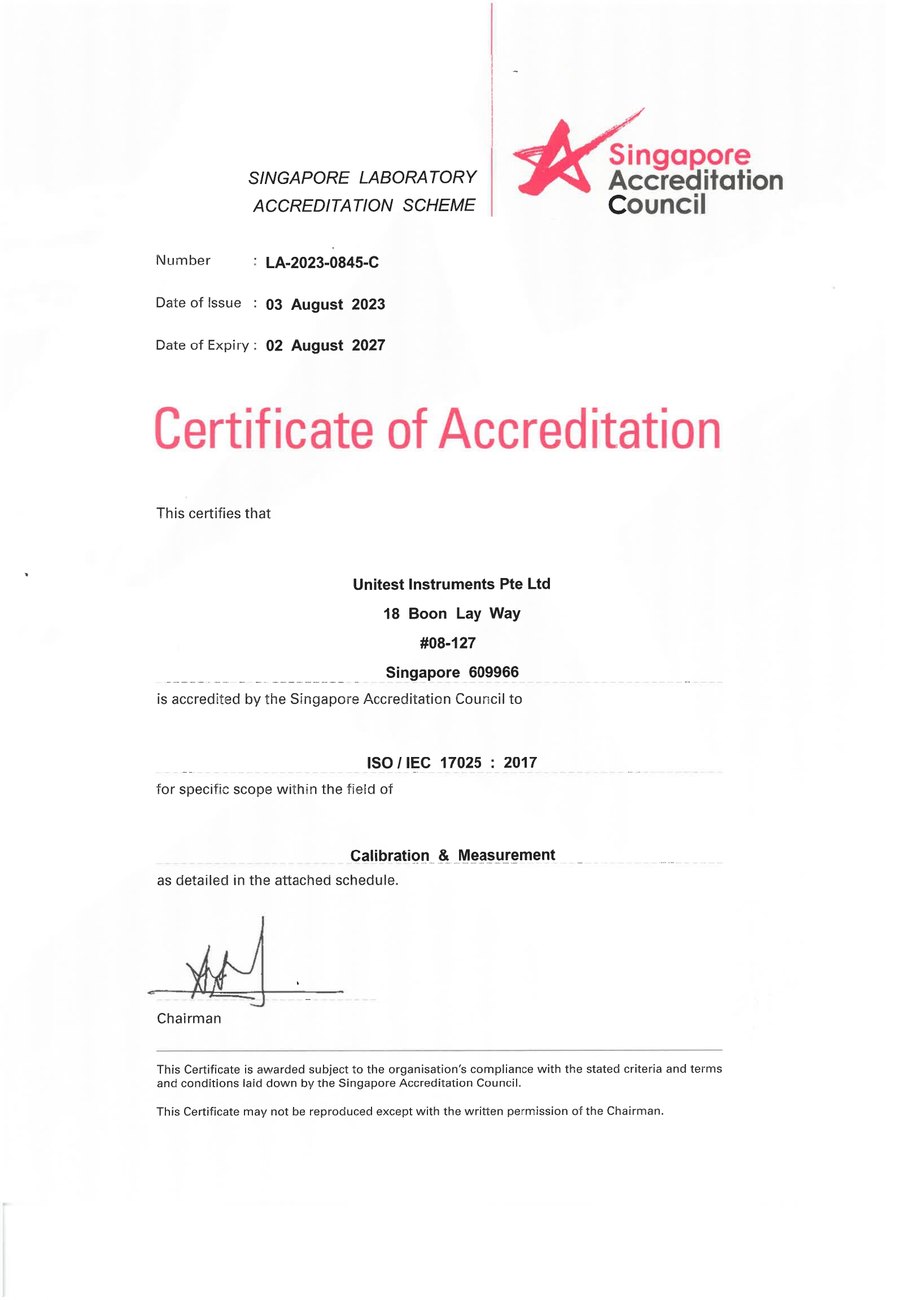
SAC-SINGLAS accredited calibration laboratory (Acc. No. LA-2023-0845-C) serving Singapore's industrial, telecom, and manufacturing sectors. All content reflects our ISO/IEC 17025 accredited scope and is reviewed by our technical calibration team.
Need RF or microwave test equipment calibrated in Singapore?
Unitest Instruments is SAC-SINGLAS accredited (Acc. No. LA-2023-0845-C) to ISO/IEC 17025. Traceable certificates accepted by ISO 9001 and industry auditors.