
Key Takeaways
- Emissivity ranges from 0 (perfect mirror) to 1.0 (perfect blackbody); most industrial instruments default to 0.95, which is only accurate for painted, oxidised, or organic surfaces.
- Polished metals have emissivities as low as 0.02–0.10, measuring them with a 0.95 setting can produce errors exceeding 50 °C at elevated temperatures.
- Emissivity is not constant: it changes with temperature, wavelength, surface oxidation, surface roughness, and angle of incidence.
- The emissivity correction formula is derived from Planck's radiation law and Stefan-Boltzmann law; errors compound nonlinearly at higher temperatures.
- Calibration of an IR thermometer must be done against a blackbody source by an accredited laboratory; emissivity compensation is a separate user responsibility.
- Singapore regulated applications (medical, pharmaceutical, building audits) require SAC-SINGLAS traceable calibration certificates for IR measurement instruments.
What Emissivity Is, and the Physics Behind It
Every object above absolute zero emits electromagnetic radiation. The quantity and spectral distribution of that radiation depends on two things: the object's temperature, and its emissivity. A perfect blackbody absorbs all incident radiation and emits the maximum possible thermal radiation at any given temperature, by definition, its emissivity is 1.0. Real materials emit less. Emissivity (symbol: ε) is the ratio of actual emission to blackbody emission at the same temperature and wavelength.
The governing equation is Planck's radiation law, which describes the spectral radiance of a blackbody as a function of temperature and wavelength. Infrared thermometers integrate this radiance over a defined waveband. Typically 8–14 µm for standard non-contact thermometers, or 3–5 µm for high-temperature applications. The instrument then solves for temperature, inserting the user-set emissivity value as a scaling factor. If ε is set to 0.95 but the actual surface is 0.30, the instrument receives only 30% of the blackbody signal but divides it as if it were 95%. Producing a temperature reading that is too low.
The Stefan-Boltzmann law (total power radiated ∝ ε × T⁴) reveals why this matters more at high temperatures: the T⁴ relationship means small fractional errors in emissivity cause large absolute temperature errors as temperature rises. At 100 °C a 0.10 emissivity error might cause a 4 °C discrepancy; at 500 °C the same emissivity error can produce a 30–40 °C discrepancy.
The Relationship Between Emissivity, Reflectivity, and Transmissivity
Kirchhoff's law of thermal radiation establishes that for any surface in thermal equilibrium, the emissivity equals the absorptivity. For an opaque surface (transmissivity τ = 0), the conservation of energy requires:
ε + ρ = 1
where ρ is the reflectivity. This is the central relationship driving measurement errors. A polished aluminium surface has a reflectivity of approximately 0.92–0.97 in the mid-infrared, giving it an emissivity of only 0.03–0.08. When an IR thermometer is pointed at it, the instrument is predominantly measuring reflected radiation from the surrounding environment (walls, equipment, personnel), rather than the temperature of the aluminium itself.
For materials that transmit infrared radiation (such as thin polyethylene films or certain glass formulations), τ is non-zero and all three components must be considered. Standard IR thermometers operating in the 8–14 µm waveband cannot see through glass (which is opaque in this band), but specialised instruments at 3.43 µm can measure through polyethylene film. A distinction critical in packaging and pharmaceutical manufacturing.
Emissivity Values for Common Industrial Materials
The following table provides indicative emissivity values for common materials in the 8–14 µm waveband at moderate temperatures (20–100 °C unless noted). These are reference values; actual emissivity should be verified by measurement for critical applications.
| Material / Surface | Emissivity (ε) Range | Measurement Risk | Recommended Approach |
|---|---|---|---|
| Human skin | 0.97–0.99 | Very low | Default 0.95–0.98 setting adequate |
| Black paint / black anodised | 0.95–0.98 | Very low | Default 0.95 setting adequate |
| Concrete / brick | 0.90–0.97 | Low | Default setting adequate for most uses |
| Wood (natural) | 0.85–0.95 | Low | Set ε = 0.90; verify on sample |
| Rubber / plastics | 0.86–0.95 | Low–moderate | Verify; some plastics are IR-transmissive |
| Oxidised steel (dark) | 0.70–0.90 | Moderate | Set ε = 0.80; re-verify after surface changes |
| Oxidised copper | 0.60–0.80 | Moderate–high | Verify against contact reference |
| Polished stainless steel | 0.10–0.35 | Very high | Use contact sensor or apply emissivity tape |
| Polished aluminium | 0.03–0.10 | Extreme | IR not recommended; use contact thermometry |
| Polished copper / gold | 0.01–0.05 | Extreme | IR not suitable without surface treatment |
Need traceable calibration for your IR thermometer or pyrometer?
Unitest Instruments calibrates non-contact infrared thermometers using blackbody radiation sources traceable to Singapore's NMC. Same-week turnaround. Certificates accepted by ISO 9001 auditors.
How Emissivity Errors Propagate Through Your Measurement
Understanding the magnitude of emissivity errors is essential for anyone making process or compliance decisions based on IR temperature data. The apparent temperature (Tapparent) read by an instrument calibrated against a blackbody is related to the true temperature (Ttrue) and emissivity (ε) through a waveband-integrated form of Planck's equation. For practical purposes in the 8–14 µm band, a useful approximation for the temperature error introduced by a wrong emissivity setting (εset instead of εtrue) at temperature T is:
ΔT ≈ T × (ln εtrue − ln εset) / C₂ / λeff
where C₂ is the second radiation constant (14,388 µm·K) and λeff is the effective wavelength. At 200 °C (473 K) with εtrue = 0.30 and εset = 0.95, the indicated temperature is approximately 147 °C. An error of 53 °C on a process that may have a specification window of ±5 °C. This is not an instrument failure; it is an operator or procedure failure in emissivity setting.
This error class is the reason that measurement uncertainty budgets for IR thermometry must explicitly include an emissivity uncertainty component. ISO/IEC 17025 requires that all contributors to uncertainty are identified and quantified; emissivity is frequently the dominant contributor for non-contact temperature measurements on metallic surfaces.
How to Determine Correct Emissivity in Practice
Method 1: Reference contact sensor
This is the most reliable field method. Attach a calibrated thermocouple or PT100 RTD to the surface and allow the system to reach thermal equilibrium. Point the IR thermometer at the same location and adjust its emissivity setting until the IR reading matches the contact reference. Record the emissivity value for future measurements of the same surface. This method is mandated by ASTM E1933 (Standard Practice for Measuring and Compensating for Emittance of a Surface Using a Radiation Thermometer and a Reference Contact Sensor).
Method 2: Emissivity tape or black paint patch
Apply a strip of commercially available emissivity reference tape (ε = 0.95 ± 0.01, per manufacturer specification) or flat black paint to the target surface. Allow it to reach thermal equilibrium with the underlying material (important. Do not measure immediately after application). Measure the IR temperature over the tape using ε = 0.95. This gives the true surface temperature. Now point the instrument at the bare surface and adjust ε until the same temperature is displayed. This method is quick and effective for field use but requires that the tape or paint genuinely equilibrates with the surface. Thermal resistance between tape and substrate can introduce error on rapidly changing or poorly conducting surfaces.
Method 3: Known-temperature cavity
For laboratory applications, a blackbody cavity source provides a surface with ε ≥ 0.995. Calibration of IR instruments against a blackbody source at multiple temperature points verifies the instrument's electro-optical accuracy independent of emissivity. This is the calibration method used by accredited laboratories. As explained in our article on what a calibration certificate covers, the certificate documents the instrument's accuracy against a reference standard. It does not automatically validate the emissivity setting you use in the field.
Relevant Standards and Regulatory Context
Several international standards govern the measurement and reporting of emissivity and the calibration of radiation thermometers:
- ASTM E1933. Standard Practice for Measuring and Compensating for Emittance of a Surface Using a Radiation Thermometer and a Reference Contact Sensor. Defines the contact-reference method.
- ASTM E1965. Standard Specification for Infrared Thermometers for Intermittent Determination of Patient Temperature. Governs medical IR thermometers; specifies accuracy requirements of ±0.2 °C.
- ISO 80601-2-56. Medical electrical equipment: Particular requirements for basic safety and essential performance of clinical thermometers for body temperature measurement. Referenced by HSA Singapore for type approval of medical thermometers.
- ASTM E2847. Standard Practice for Calibration and Accuracy Verification of Wideband Infrared Thermometers. Covers field verification procedures.
- IEC 62942. Industrial process measurement and control: radiation thermometers. Provides definitions and performance requirements.
- VDI/VDE 3511 Part 4.3. Temperature measurement in industry: radiation thermometry. A widely cited German engineering standard with detailed emissivity tables and uncertainty guidance.
In Singapore, the Health Sciences Authority (HSA) requires medical IR thermometers to meet ASTM E1965 or ISO 80601-2-56 specifications and to be calibrated to ensure traceability. For non-medical industrial applications, Enterprise Singapore's SAC accreditation framework requires that calibration certificates issued for regulatory or contractual purposes come from ISO/IEC 17025 accredited laboratories. The basis on which Unitest Instruments (Acc. No. LA-2023-0845-C) operates. Understanding the difference between accredited and non-accredited calibration is critical when IR thermometry data is used for regulatory submissions, quality audits, or contractual compliance.
Emissivity in Calibration: What Accredited Labs Actually Do
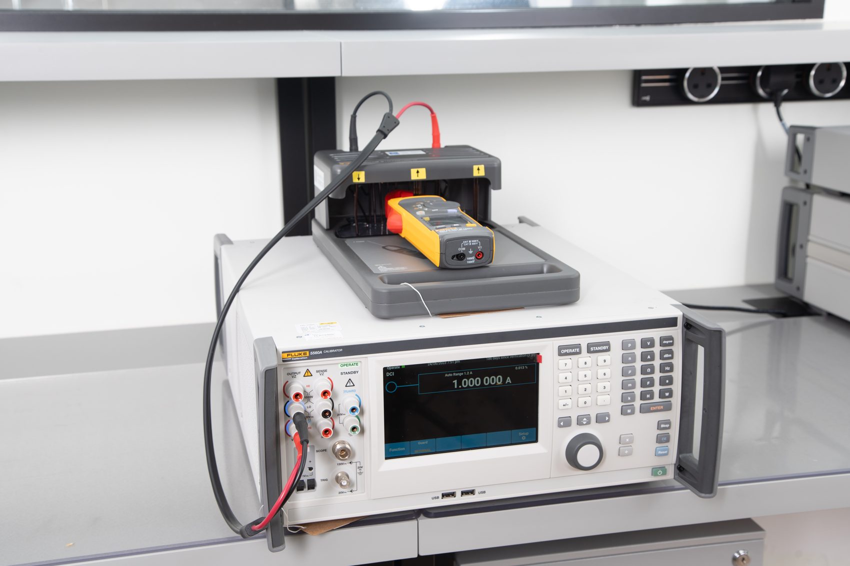
When Unitest Instruments calibrates an infrared thermometer, the procedure follows a structured protocol aligned with ASTM E2847 and the laboratory's accredited scope. A blackbody radiation source (a cavity furnace or flat-plate blackbody), is set to a series of target temperatures spanning the instrument's stated range. The cavity or plate achieves an effective emissivity of 0.995 or higher, making emissivity compensation effectively irrelevant for the calibration measurement itself. The instrument's emissivity setting is configured to 1.00 (or 0.95, depending on the instrument design and laboratory procedure) and the indicated temperature at each set-point is compared against the reference temperature, which is itself traceable to Singapore's National Metrology Centre via a calibrated transfer standard pyrometer or thermocouple.
The measurement uncertainty of the calibration (which must be reported on the calibration certificate per ISO/IEC 17025), captures contributions from the blackbody temperature uncertainty, the stability of the blackbody source, the repeatability of the instrument under test, and the resolution of its display. Emissivity uncertainty in the field measurement is separate and is the responsibility of the end user to quantify and control. This distinction is often misunderstood: a certificate that says ±0.5 °C at ε = 0.95 does not mean the instrument will read within ±0.5 °C on a polished steel surface set to ε = 0.30.
For calibration intervals and when to recalibrate your IR thermometer, our article on how often to calibrate instruments provides a risk-based framework applicable to non-contact temperature devices.
Common Mistakes and How to Avoid Them
The following errors account for the majority of IR measurement failures encountered in industrial and laboratory settings:
- Using the factory default emissivity (typically 0.95) on all surfaces. This is accurate for skin, paint, and most organic materials but causes large errors on metals. Always verify the target material and adjust accordingly.
- Ignoring reflected background radiation. In environments with hot furnaces, boilers, or radiant heaters nearby, reflective surfaces will pick up the reflected IR signature of those heat sources. Shield the measurement zone or use an IR thermometer with a narrow field of view to minimise background interference.
- Measuring through contaminated optics. Condensation, oil films, dust, or scratches on the instrument's lens reduce the measured signal and cause the instrument to underread. Clean and inspect optics regularly; check the optical path as part of routine maintenance.
- Violating the distance-to-spot-size (D:S) ratio. Every IR thermometer has a D:S ratio (e.g. 12:1 means the measurement spot is 1/12 of the distance to the target). If the target is smaller than the spot, the reading is averaged with the surrounding area temperature. On small targets, the displayed temperature will be pulled toward the background, not the target.
- Measuring through steam, smoke, or CO₂-rich atmospheres. These gases absorb infrared radiation in the 8–14 µm band and cause the instrument to read low. Use instruments with wavebands that avoid atmospheric absorption windows, or purge the optical path.
- Not accounting for emissivity change with surface condition. A machined steel part has low emissivity; the same part after heat treatment and oxidation has much higher emissivity. Emissivity settings valid for one production stage may be wrong at another.
Directional Emissivity: Why Viewing Angle Matters
Emissivity is often treated as a single fixed number for a given material, but for many real surfaces it is genuinely directional, meaning the effective emissivity a sensor detects changes with the angle between the instrument's line of sight and the surface normal. For most rough, non-metallic materials (concrete, wood, oxidised surfaces), emissivity remains reasonably constant across viewing angles up to roughly 45 degrees from normal, after which it begins to fall noticeably as the angle steepens. Metals and other low-emissivity surfaces are far more sensitive to this effect, and can show significant emissivity swings even at moderate angles, compounding the already large uncertainty these materials present for infrared measurement. This is a genuine physical effect grounded in the same electromagnetic theory that governs reflectivity, not an instrument artefact, and it means that a technician who determines a correct emissivity setting for a surface while standing directly in front of it may introduce meaningful error by taking subsequent readings from a steep angle for convenience or access reasons.
The practical guidance that follows from this is straightforward: wherever feasible, position the infrared thermometer as close to perpendicular to the target surface as site conditions allow, and if a steep viewing angle is unavoidable (measuring an overhead pipe run from floor level, for instance), determine the emissivity setting using the contact-reference method at that same working angle rather than assuming a value determined head-on will transfer unchanged. For repeat measurements at a fixed monitoring point, such as a permanently mounted process IR sensor, this is a one-time calibration consideration; for a technician conducting a walking survey across many targets at varying angles, it is a source of measurement inconsistency worth flagging in the survey methodology and, where precision matters, worth verifying with spot checks at representative angles.
Building a Practical Emissivity Reference Table for Your Facility
Published emissivity tables, including the one earlier in this article, are a reasonable starting point but are not a substitute for facility-specific verification, because emissivity depends on surface finish, oxidation state, contamination, paint formulation, and even manufacturing batch in ways generic tables cannot fully capture. A facility that relies heavily on infrared thermometry for process control or predictive maintenance benefits from building its own verified emissivity reference table for the specific surfaces it measures repeatedly: motor housings, electrical panel covers, specific pipe insulation jacketing, particular equipment enclosures. Using the contact-reference or emissivity-tape method described above, a technician can determine and record the correct emissivity setting for each recurring target once, then apply that verified value consistently on every subsequent measurement, removing a major source of variability between different operators and different survey dates.
This table should be treated as a living document and revisited whenever a surface's condition changes materially, after repainting, after a period of oxidation or corrosion, or after equipment replacement with a different material or finish, since the whole point of the exercise is that emissivity is a property of the actual surface being measured today, not a generic material property that holds indefinitely. Facilities running formal predictive maintenance or condition monitoring programmes that feed infrared data into trend analysis should treat an unverified change in a target's emissivity as a possible confounding factor whenever a trend shows an unexplained step change, since a re-painted surface or a newly oxidised patch can produce an apparent temperature shift that has nothing to do with the equipment's actual thermal condition.
Frequently Asked Questions
Emissivity is a dimensionless number from 0 to 1 that describes how efficiently a surface emits thermal radiation compared to a perfect blackbody (emissivity = 1.0). An IR thermometer measures the infrared energy emitted by a surface and converts it to a temperature reading. If the emissivity setting in the instrument does not match the actual emissivity of the target material, the conversion calculation is wrong and the displayed temperature will be incorrect. Sometimes by 20–50 °C or more on reflective metal surfaces.
Polished stainless steel has an emissivity of approximately 0.10–0.35, depending on surface finish and alloy. This is one of the most challenging materials to measure with an IR thermometer. Using the default setting of 0.95 on polished stainless steel will cause the instrument to significantly underread the true temperature. Best practice is to use a contact thermocouple or RTD reference at a known temperature, then adjust the IR instrument's emissivity setting until its reading matches. Or apply an emissivity tape (ε ≈ 0.95) to the surface and measure over the tape.
Yes. Emissivity is not a fixed constant for most materials. It varies with temperature, wavelength of radiation, surface condition, and angle of measurement. For example, the emissivity of oxidised steel changes from approximately 0.70 at 200 °C to 0.85 at 600 °C. This means a single emissivity setting is only accurate within a limited temperature range. For precision work across a wide temperature range, emissivity tables or wavelength-specific pyrometers are required.
For any surface, emissivity (ε), reflectivity (ρ), and transmissivity (τ) must sum to 1.0: ε + ρ + τ = 1. For opaque materials, τ = 0, so ε + ρ = 1. A highly reflective surface (like polished aluminium, ρ ≈ 0.95) has a very low emissivity (ε ≈ 0.05) and will appear to be near ambient temperature to an IR thermometer because it is mostly reflecting the environment rather than emitting its own heat. This is why polished metals are the most common cause of IR measurement errors in industrial settings.
The standard method is to heat the material to a known temperature (verified by a contact sensor such as a calibrated thermocouple or RTD), then adjust the emissivity setting on the IR thermometer until its displayed temperature matches the reference. Alternatively, apply a strip of black electrical tape or dedicated emissivity tape (ε ≈ 0.95) to the material surface, allow it to reach thermal equilibrium, and measure over the tape. The ASTM E1933 standard provides a detailed procedure for determining emissivity using both approaches.
IR thermometers require calibration of their temperature measurement accuracy, typically performed using a blackbody radiation source set to a known temperature (emissivity ≈ 1.0). The calibration verifies the instrument's signal-processing accuracy. Emissivity compensation is a separate user-configured parameter. Even a perfectly calibrated IR thermometer will give wrong readings if the emissivity setting is incorrect for the target material. Calibration should be performed by an ISO/IEC 17025 accredited laboratory to ensure traceability to national measurement standards.
Approximate emissivity values at ambient-to-moderate temperatures in the 8–14 µm waveband: human skin 0.98, black paint 0.95–0.98, concrete and brick 0.90–0.95, wood 0.85–0.95, rubber 0.86–0.95, oxidised copper 0.60–0.80, oxidised steel 0.70–0.85, polished aluminium 0.03–0.10, polished copper 0.02–0.05, polished stainless steel 0.10–0.35. These values are indicative. Always verify with a reference measurement for critical applications.
In Singapore, non-contact infrared thermometers used in regulated applications (including medical screening, pharmaceutical cold-chain monitoring, building energy audits, and industrial safety systems), should be calibrated by a SAC-SINGLAS accredited laboratory to ensure traceability to Singapore's National Metrology Centre (NMC). The Health Sciences Authority (HSA) and Enterprise Singapore both reference SAC accreditation as the basis for measurement traceability claims. Medical IR thermometers are additionally governed by ISO 80601-2-56 and ASTM E1965, which specify accuracy requirements verifiable only through traceable calibration.
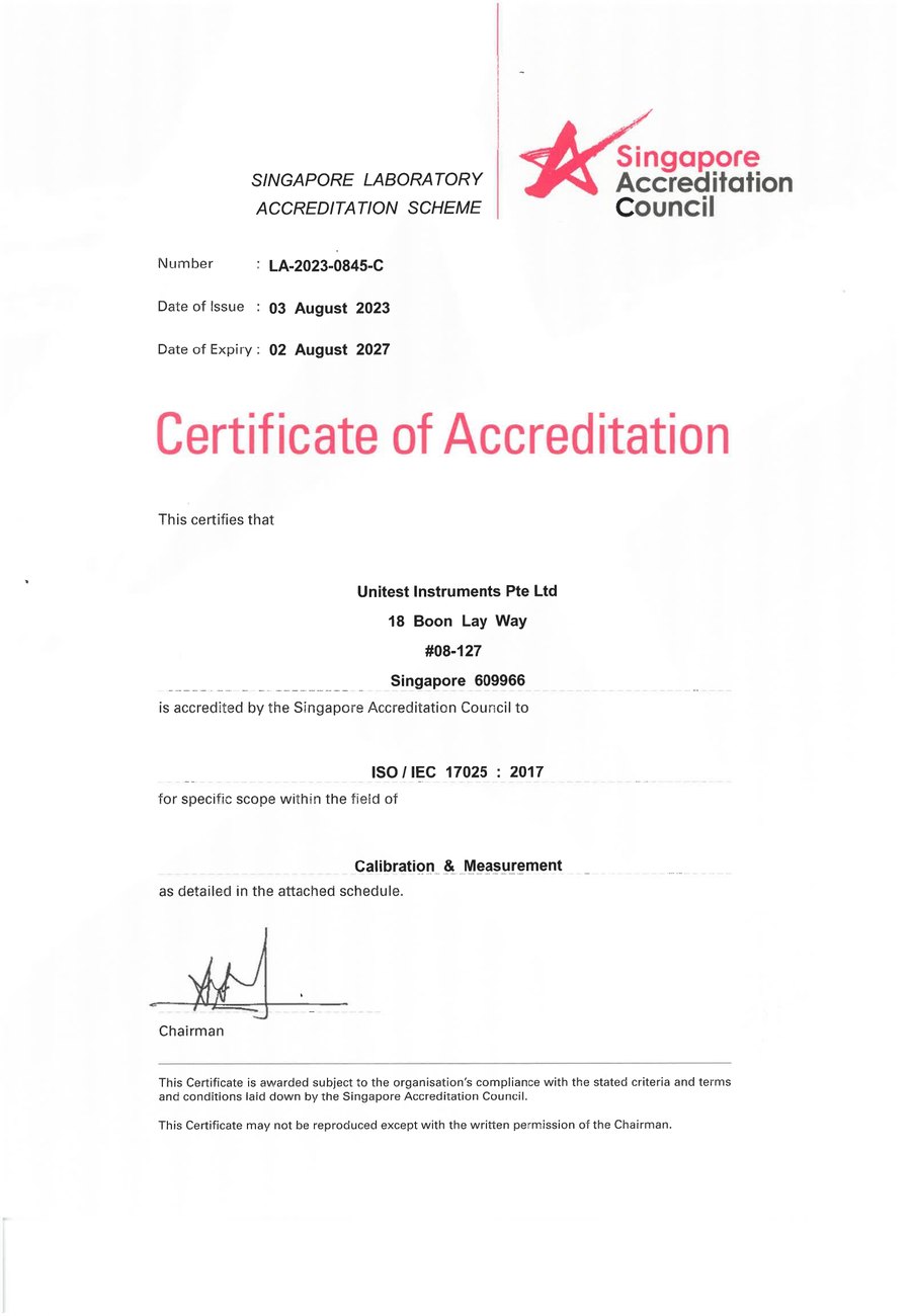
SAC-SINGLAS accredited calibration laboratory (Acc. No. LA-2023-0845-C) serving Singapore's industrial, pharmaceutical, and manufacturing sectors. All content reflects our ISO/IEC 17025 accredited scope and is reviewed by our technical calibration team.
Need IR thermometer calibration in Singapore?
Unitest Instruments is SAC-SINGLAS accredited (Acc. No. LA-2023-0845-C) to ISO/IEC 17025. Same-week turnaround, certificates accepted by ISO 9001 auditors.