
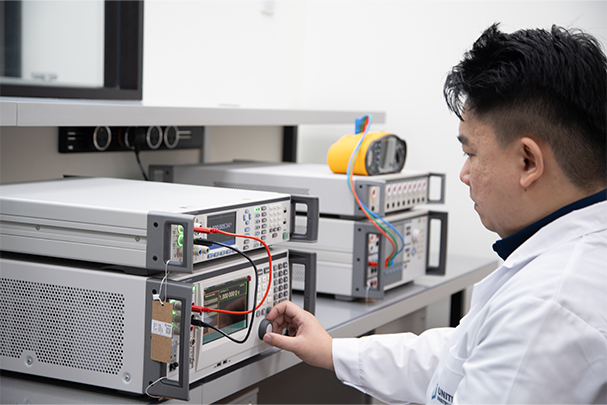
Key Takeaways
- Dielectric withstand (hi-pot) is a destructive-stress pass/fail test governed by IEC 60243-1/2; insulation resistance is a diagnostic measurement governed by IEC 60364-6 and BS 7671.
- Always screen with insulation resistance first. A reading below 1 MΩ means the equipment should not be subjected to hi-pot voltage, which could cause catastrophic breakdown.
- In Singapore, both tests are relevant to SS 638 compliance, MOM Workplace Safety and Health regulations, and the SAFETY mark scheme for controlled goods.
- Polarisation Index (PI = R₁₀ min / R₁ min) greater than 2.0 indicates healthy insulation in motors and transformers (per IEEE Std 43-2013).
- Instruments used for both tests must be calibrated at accredited intervals. Uncalibrated hi-pot testers are a common reason for failed third-party safety audits in Singapore.
Definitions and Fundamental Distinction
At their core, the two tests interrogate insulation in entirely different ways. Dielectric withstand testing (also called hi-pot (high-potential) testing, electric strength testing, or voltage withstand testing), applies a voltage significantly above the equipment's rated operating voltage for a controlled duration. The purpose is to force latent defects to manifest as breakdown events before the equipment reaches the field. If the insulation survives without the measured leakage current exceeding a preset trip threshold, the test is a pass. If breakdown occurs (evidenced by arcing, a sudden current surge, or a trip), the test is a fail and the unit is rejected.
Insulation resistance (IR) testing applies a comparatively modest DC voltage (most commonly 500 V DC for low-voltage circuits and 1000 V DC for higher-rated systems), and measures the resulting leakage current after a defined soak period (typically 1 minute). Ohm's law converts that current reading into a resistance value expressed in megaohms (MΩ) or gigaohms (GΩ). A high resistance means little leakage and healthy insulation; a declining resistance over repeated tests, or a reading below the acceptance threshold, flags degraded insulation that requires investigation or replacement.
The conceptual distinction matters enormously in practice: hi-pot is a stress test that pushes insulation beyond normal operating limits to find weaknesses; IR testing is a condition test that characterises the insulation state under a benign voltage. Neither test can substitute for the other.
Physics and Chemistry Behind the Tests
Insulating materials (polymers such as PVC, XLPE, PTFE, and epoxy resins; natural materials such as mica and oil-impregnated paper), resist current flow because their electrons are tightly bound and not free to migrate. The bulk resistivity of high-grade epoxy is typically 10¹⁴ to 10¹⁶ Ω·cm, while air has a dielectric strength of approximately 3 kV/mm under standard conditions.
When a high electric field is applied during a withstand test, several degradation mechanisms can produce breakdown. Partial discharge (PD) occurs when the field inside a gas void within the insulation exceeds the local ionisation threshold (roughly 1–3 kV/mm for air), generating electron avalanches that erode the surrounding polymer through UV radiation and ozone attack. Thermal breakdown occurs when resistive heating from leakage current raises the local temperature faster than the material can dissipate it, reducing resistivity and accelerating current flow in a positive-feedback loop. Electromechanical breakdown occurs in soft elastomers when the electrostatic compressive stress exceeds the material's yield strength, thinning the insulation until it punctures.
In an insulation resistance test, the measured current has three components: capacitive charging current (decays within seconds), polarisation absorption current (decays over minutes as molecular dipoles align with the field), and true conduction current (the DC leakage that persists). The one-minute reading is used as a standard reference because the capacitive transient has largely subsided, giving a more stable conduction-dominated reading. The ten-minute reading, used to compute the Polarisation Index, captures most of the absorption current decay.
Governing Standards and Acceptance Criteria
Singapore uses a combination of international IEC standards, adopted British Standards, and local SS codes. The table below summarises the primary standards relevant to both tests.
| Standard | Test Type | Scope | Key Acceptance Criterion |
|---|---|---|---|
| IEC 60243-1 | Dielectric Withstand | Insulating materials, AC short-time and step-up methods | No breakdown at specified voltage; electric strength > material specification |
| IEC 60243-2 | Dielectric Withstand | DC test methods for insulating materials | No breakdown at specified DC voltage for specified duration |
| IEC 61010-1 | Dielectric Withstand | Laboratory and measurement equipment | 1.5× rated voltage + 1000 V for 5 s; no flashover |
| IEC 60335-1 | Dielectric Withstand | Household appliances | 1250 V AC for 1 min between live parts and accessible surfaces |
| IEC 60364-6 / BS 7671 | Insulation Resistance | LV electrical installations | ≥1 MΩ for circuits up to 500 V; ≥1 MΩ/kV for higher voltages |
| IEEE Std 43-2013 | Insulation Resistance | Rotating machines | PI ≥ 2.0; minimum IR corrected to 40 °C ≥ (kV rating + 1) MΩ |
| SS 638 | Both | Singapore electrical installations | References IEC 60364 series; IR ≥ 1 MΩ; withstand per equipment standard |
For product safety compliance under Singapore's Consumer Protection (Safety Requirements) Regulations, the SAFETY mark scheme requires demonstration of dielectric strength per the applicable product standard. Test certificates issued by SAC-SINGLAS-accredited laboratories are accepted directly by Enterprise Singapore.
Measurement Methods and Instrument Setup
Dielectric Withstand Test Procedure
A hi-pot tester generates a controlled high voltage from a high-voltage transformer (AC test) or a voltage-multiplier circuit (DC test). The test voltage is applied between the conductor under test and the equipment chassis/earth, or between isolated conductors. The ramp rate matters: IEC 60243-1 specifies that for short-time tests, voltage should be raised at a rate of 500 V/s to 1000 V/s to the test level, then held for the specified time (commonly 60 seconds for material testing, 1 to 5 seconds for production-line testing of assembled equipment).
The instrument monitors leakage current continuously. A typical production hi-pot tester trips at leakage currents above 1–10 mA AC or 3–5 mA DC, depending on the standard. The key calibration parameters are: output voltage accuracy (typically ±2% of reading), leakage current measurement accuracy (typically ±5% of reading), and trip threshold repeatability. An uncalibrated hi-pot tester may be applying 1100 V when the panel reads 1000 V. Potentially stressing borderline product into failure, or worse, releasing defective product because the actual voltage was below the required level.
Insulation Resistance Test Procedure
A megohmmeter (insulation resistance tester) applies a stabilised DC voltage and measures current with a high-sensitivity electrometer circuit. Modern digital instruments provide direct readout in MΩ or GΩ. The standard test sequence for a motor winding is: disconnect the winding from the drive circuit, connect the megohmmeter between the winding and the motor frame (earth), apply the test voltage, and record the reading at 1 minute (IR₁) and 10 minutes (IR₁₀). Divide IR₁₀ by IR₁ to obtain the Polarisation Index.
Temperature correction is critical: insulation resistance approximately halves for every 10 °C rise in temperature. IEEE Std 43-2013 provides correction factors to normalise readings to 40 °C for comparison. For a meaningful trending programme, always measure at a consistent temperature or apply the correction factor rigorously.
As discussed in our article on what a calibration certificate covers, the measurement uncertainty of the megohmmeter must be declared on the calibration certificate. For high-resistance measurements in the gigaohm range, guard connections are essential. Without the guard electrode, surface leakage currents across the test fixture add directly to the measured current, causing the instrument to read a falsely low resistance.
Calibrate Your Hi-Pot and IR Testers in Singapore
Unitest Instruments (Acc. No. LA-2023-0845-C) provides accredited calibration of dielectric withstand testers and insulation resistance meters with full uncertainty statements. Accepted by ISO 9001 auditors and Singapore MOM inspectors.
Calibration Implications for Both Tests
Both hi-pot testers and megohmmeters are measuring instruments subject to drift, and both must be calibrated at intervals traceable to national standards. In Singapore, the National Metrology Centre (NMC) maintains the primary voltage and resistance standards; SAC-SINGLAS-accredited laboratories such as Unitest Instruments (Acc. No. LA-2023-0845-C) provide calibrations traceable to NMC.
For hi-pot testers, calibration checks include: output voltage at multiple points across the instrument range, voltage stability during the hold period, leakage current measurement accuracy, and the trip threshold setting. The calibration laboratory applies a precision high-voltage divider to measure the actual output, and a precision current shunt to verify the leakage current reading. Uncertainties for voltage in the kilovolt range are typically 0.5% to 2% of reading at a 95% confidence level (k=2).
For insulation resistance testers, calibration involves applying a known high-resistance standard (precision resistors ranging from 1 MΩ to 10 GΩ, housed in a guarded fixture), and comparing the instrument's reading to the reference value. The key challenge is that commercially available high-resistance standards above 1 GΩ have uncertainty contributions from temperature coefficient, humidity sensitivity, and connector leakage that must be carefully managed. Our article on measurement uncertainty explains how these contributions are combined in an uncertainty budget.
A common oversight in Singapore facilities: companies calibrate their multimeters and pressure gauges annually but neglect the hi-pot tester on the production line because it "just needs to pass or fail." This logic fails at ISO 9001 or IEC 62353 (medical electrical equipment) audits, where the auditor will ask for a current calibration certificate for every instrument that generates safety-critical test data.
Sequence, Interaction, and Common Mistakes
The correct testing sequence is non-negotiable: insulation resistance first, hi-pot second. Running hi-pot on equipment with severely degraded insulation (IR below 1 MΩ) risks violent breakdown that can damage the equipment, the test instrument, and injure the operator. The IR test is a rapid, low-energy screen; the hi-pot test is the definitive safety gate.
Mistake 1: Performing Hi-Pot on Damp Equipment
Moisture ingress dramatically reduces insulation resistance. A motor left outdoors may read 0.5 MΩ even with perfectly intact winding insulation, simply due to condensation on the end caps. Applying hi-pot voltage in this state causes surface flashover that carbonises the winding slots and causes genuine long-term damage. The correct approach is to dry the equipment (oven at 50–80 °C for several hours, or temporary heat lamps) until the IR reading recovers above 1 MΩ before proceeding.
Mistake 2: Ignoring Test Lead Capacitance in AC Hi-Pot
During an AC hi-pot test, the capacitance of long test leads and the unit under test generates a capacitive charging current that is read by the instrument as leakage. On large cable assemblies or switchgear with significant capacitance, this can trigger nuisance trips even when insulation is healthy. The solution is to use a tester with capacitive current compensation, or to switch to DC hi-pot for highly capacitive loads. Noting that DC tests reveal different failure modes and require different acceptance criteria (IEC 60243-2).
Mistake 3: Not Accounting for Temperature in IR Trending
A motor that reads 200 MΩ in January and 85 MΩ in August has not necessarily degraded. The seasonal temperature difference could fully explain the change. Without temperature-corrected trending (normalised to 40 °C per IEEE Std 43-2013), maintenance engineers may schedule unnecessary rewinding or, more dangerously, miss genuine degradation hidden by a cool ambient temperature.
Mistake 4: Confusing Leakage Current with Insulation Resistance
Some older hi-pot testers report only leakage current in milliamps; some engineers mistakenly use this reading as a proxy for insulation resistance. This is incorrect: the leakage current during a hi-pot test is measured at a fundamentally different voltage and over a different time window than the DC soak in an IR test. The two readings cannot be compared or converted without additional assumptions about the insulation's response characteristics.
Choosing the Right Test for Your Application
The choice of test is primarily dictated by the applicable product or installation standard, not by personal preference. For manufactured products sold in Singapore, the product safety standard (IEC 60335 for appliances, IEC 61010-1 for lab equipment, IEC 62368-1 for audio/video/IT equipment) specifies the exact test voltage, duration, and pass/fail criterion. The test must be reproduced with a calibrated tester.
For in-service electrical installations, SS 638 and the MOM regulations drive the regime. Insulation resistance testing is the primary periodic test for fixed wiring; hi-pot testing is generally reserved for new installations, major modifications, or when a fault has occurred. For rotating machinery (motors, generators, transformers), the IEC 60034 series and IEEE Std 43-2013 provide detailed guidance on both test types and trending programmes.
Understanding ISO/IEC 17025 calibration requirements helps facilities managers make the case internally for accredited calibration. The standard explicitly requires that all equipment that can affect measurement results must be calibrated, which encompasses both hi-pot testers and megohmmeters used in safety testing.
Frequently Asked Questions
Dielectric withstand testing (also called hi-pot or electric strength testing) applies a high voltage (typically 500 V to several kV), for a defined duration to confirm that insulation will not break down under worst-case fault conditions. Insulation resistance testing applies a lower DC voltage (commonly 500 V or 1000 V) and measures the resulting leakage current to calculate resistance in megaohms or gigaohms. The withstand test is a pass/fail stress test; the insulation resistance test is a diagnostic measurement of insulation quality.
In Singapore, dielectric withstand testing is governed by IEC 60243-1 (electric strength of insulating materials. AC methods), IEC 60243-2 (DC methods), SS 638 (Code of practice for electrical installations), and product-specific standards such as IEC 60335 for household appliances and IEC 61010-1 for laboratory equipment. The Ministry of Manpower (MOM) Workplace Safety and Health regulations also reference electrical safety testing for LVD compliance. Equipment used for the tests must be calibrated to traceable standards, as required by SS ISO/IEC 17025.
The most common test voltages for insulation resistance testing are 500 V DC for low-voltage equipment rated up to 1000 V, and 1000 V DC for higher-rated equipment or motor windings. IEC 60364-6 and BS 7671 specify a minimum insulation resistance of 1 MΩ for circuits up to 500 V, and 1 MΩ per 1000 V of rated voltage for higher systems. In practice, healthy insulation typically measures hundreds of megaohms or even gigaohms.
They are complementary but not interchangeable. Best practice is to perform insulation resistance testing first, as a low resistance reading (below 1 MΩ) indicates degraded insulation that may catastrophically fail under the high voltage of a withstand test. Only equipment that passes the insulation resistance screen should be subjected to hi-pot testing. Running them in the wrong sequence risks destroying marginal insulation (and the test instrument), unnecessarily.
Calibration intervals depend on instrument manufacturer recommendations, usage intensity, and the consequences of measurement error. A typical interval is 12 months for instruments used in regular production or field testing, and 6 months for critical safety-of-life applications. Under ISO/IEC 17025, calibration must be traceable to national standards. In Singapore, Unitest Instruments (SAC-SINGLAS Acc. No. LA-2023-0845-C) provides accredited calibration of hi-pot testers and insulation resistance testers with full measurement uncertainty statements.
Failure modes include: (1) Partial discharge (corona) in air voids within insulation, which erodes the dielectric over time; (2) Thermal degradation from elevated operating temperatures that breaks polymer chains; (3) Moisture ingress that creates conductive pathways; (4) Mechanical damage from vibration, bending fatigue, or chemical contamination; (5) Manufacturing defects such as pinholes, inclusions, or insufficient creepage distances. A sudden increase in leakage current above the trip threshold during the withstand test indicates breakdown.
Polarisation Index (PI) is the ratio of the insulation resistance measured at 10 minutes to that measured at 1 minute, using the same test voltage. A PI above 2.0 is generally considered acceptable for rotating machines and transformer windings (per IEEE Std 43-2013). A PI below 1.0 indicates contaminated or moisture-saturated insulation. The PI provides more diagnostic information than a single-point resistance reading because it reflects how the polarisation current in the insulation decays over time. Healthy insulation shows a significant rise in resistance, while degraded insulation levels off quickly.
Yes. The Workplace Safety and Health (Electrical Installations) Regulations 2009 require that electrical installations and equipment used at workplaces meet the requirements of SS 638 (Code of practice for electrical installations). Controlled goods under the Consumer Protection (Safety Requirements) Regulations must carry a SAFETY mark and pass safety tests (which include dielectric strength and insulation resistance), before sale in Singapore. Test certificates from accredited laboratories such as SAC-SINGLAS-accredited bodies carry regulatory weight with the Singapore Safety Authority (SAFETY mark scheme administered by Enterprise Singapore).
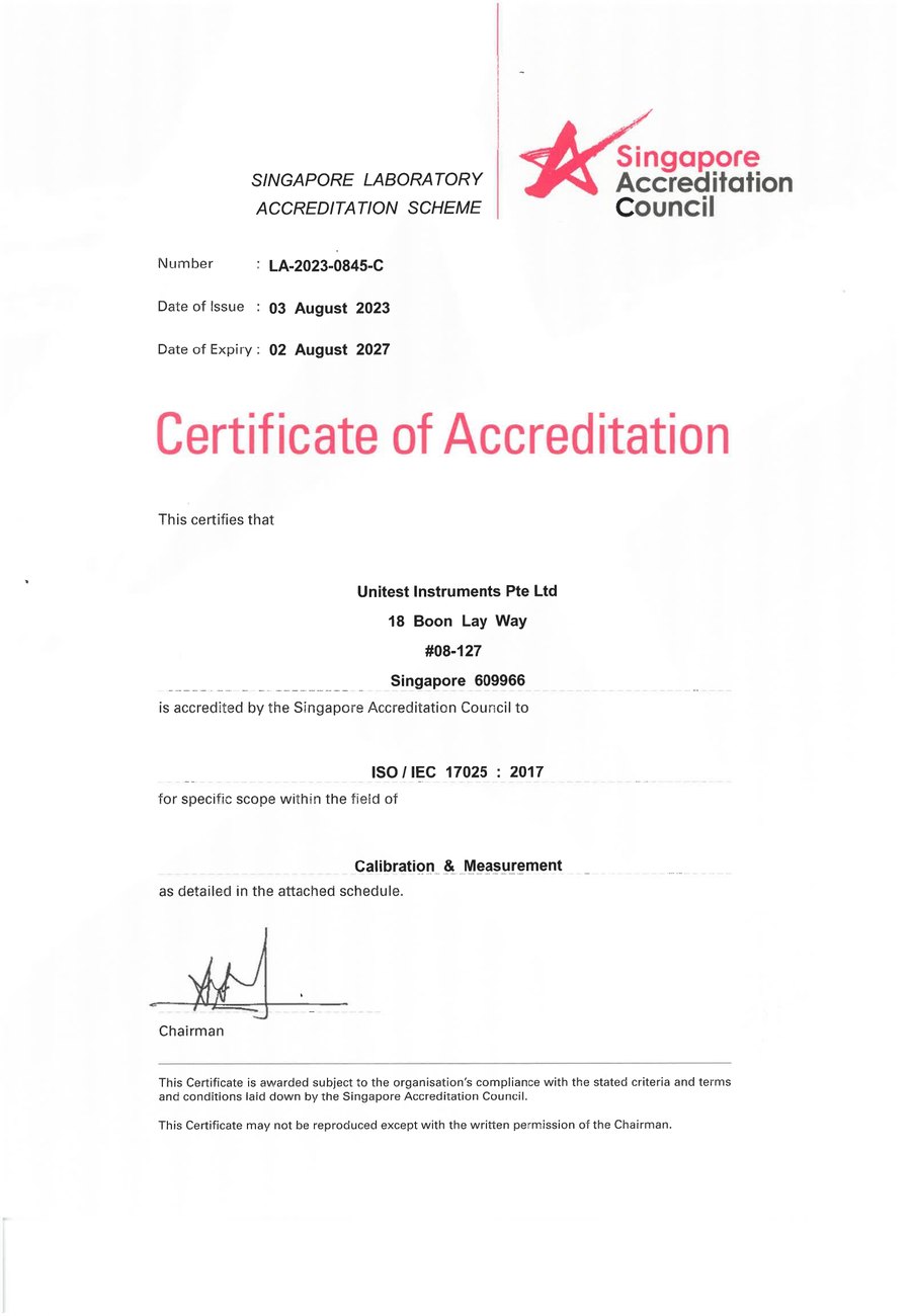
SAC-SINGLAS accredited calibration laboratory (Acc. No. LA-2023-0845-C) serving Singapore's industrial, pharmaceutical, and manufacturing sectors. All content reflects our ISO/IEC 17025 accredited scope and is reviewed by our technical calibration team.
Need electrical safety instrument calibration in Singapore?
Unitest Instruments is SAC-SINGLAS accredited (Acc. No. LA-2023-0845-C) to ISO/IEC 17025. Same-week turnaround, certificates accepted by ISO 9001 auditors and Singapore MOM inspectors.