
Key Takeaways
- UTT uses sound pulse time-of-flight and the material's acoustic velocity to calculate wall thickness from a single surface, with typical resolutions of 0.01 mm on steel.
- The governing standards are ASTM E797 (contact pulse-echo method) and ISO 16809 (general ultrasonic thickness measurement); calibration laboratories must meet ISO/IEC 17025.
- Acoustic velocity varies significantly between materials (5,920 m/s in mild steel versus 2,700 m/s in HDPE), so the correct velocity setting is critical to every reading.
- In Singapore, pressure vessel statutory examinations under MOM's WSH Regulations require metrologically traceable UTT equipment, fulfilled by SAC-SINGLAS accredited calibration.
- The five most common field errors (wrong velocity, air gaps, uncorrected zero offset, paint-layer inflation, and temperature-induced drift), are all preventable with a proper calibration and procedure discipline.
What Is Ultrasonic Thickness Testing?
Ultrasonic thickness testing (UTT), sometimes called ultrasonic wall thickness measurement, is a form of non-destructive testing (NDT) that determines the thickness of a solid material by timing the round-trip travel of a high-frequency sound pulse through it. Unlike mechanical gauges or calipers, UTT requires access to only one face of the component. A property that makes it indispensable for in-service inspection of pressurised systems, buried pipework, coated structures, and any component where the back wall is permanently inaccessible.
The technique was first applied industrially in the late 1940s and has since become the backbone of corrosion engineering and asset integrity programmes worldwide. In Singapore's petrochemical, utilities, semiconductor-fab, and pharmaceutical manufacturing sectors, UTT readings form the primary data stream feeding fitness-for-service (FFS) assessments under standards such as API 579-1/ASME FFS-1 and the local Workplace Safety and Health Act frameworks. The core principle is simple, but the measurement discipline required to generate reliable, traceable data is substantial, and is the focus of this article.
The Physics: How Sound Becomes a Thickness Reading
Every UTT measurement rests on the equation t = v × (T/2), where t is wall thickness, v is the longitudinal acoustic velocity of the material, and T is the round-trip travel time of the pulse. A piezoelectric transducer converts an electrical spike into a mechanical pressure wave, which propagates through a couplant gel into the test piece. When the wave reaches the far surface (the back wall), the acoustic impedance mismatch between steel and air causes almost total reflection. The reflected wave returns to the transducer, which converts it back to an electrical signal, the back-wall echo. The gauge's timing circuit measures the interval between transmission and reception, divides by two (for the return trip), and multiplies by the stored velocity value to produce a thickness reading.
Acoustic Velocity. The Critical Variable
Acoustic velocity is not a universal constant. It varies with material composition, grain structure, and temperature. The table below lists longitudinal velocities for common industrial materials. An incorrectly programmed velocity is the single most consequential calibration error in field UTT. A 5% velocity error produces a 5% thickness error, which on a 10 mm wall reads as 9.5 mm or 10.5 mm. At a 5 mm minimum-acceptable wall threshold, that error could determine whether an asset passes or fails a fitness-for-service assessment.
| Material | Longitudinal Velocity (m/s) | Typical UTT Frequency (MHz) | Common Application |
|---|---|---|---|
| Mild / Carbon Steel | 5,900 – 5,960 | 5 | Pipework, pressure vessels, structural |
| Stainless Steel (304/316) | 5,740 – 5,800 | 5 – 10 | Pharmaceutical, food processing |
| Aluminium (wrought) | 6,300 – 6,350 | 5 – 10 | Aerospace, heat exchangers |
| Copper | 4,660 – 4,720 | 5 | Heat exchangers, electrical bus |
| Cast Iron (grey) | 4,500 – 5,600 | 1 – 2.25 | Legacy pipework, machine beds |
| HDPE | 2,430 – 2,700 | 1 – 2.25 | Water mains, chemical dosing lines |
| Glass (borosilicate) | 5,570 – 5,640 | 10 – 20 | Sight glasses, pharmaceutical vessels |
Temperature adds a further complication: acoustic velocity in steel decreases by approximately 0.5 m/s per °C above 20 °C. On process pipework running at 150 °C, an uncompensated gauge will overestimate thickness by roughly 1.1%. This is small in absolute terms on thick-walled pipe but grows into a meaningful error on thin-walled tubing or near minimum-acceptable wall limits. High-temperature probes with delay lines, and electronic temperature-compensation curves, exist precisely to address this.
Transducer Selection and Probe Technology
The transducer (probe) is the interface between the electronic gauge and the physical world, and its selection strongly influences measurement quality. The two dominant probe configurations for contact UTT are single-element and dual-element (pitch-catch). Single-element probes use one crystal for both transmitting and receiving; they perform best on smooth, parallel surfaces with thicknesses above approximately 3 mm. Dual-element probes have separate transmit and receive crystals angled slightly inward, which eliminates the "dead zone" near the front face and makes them better suited for thin materials (down to approximately 0.5 mm), rough or corroded surfaces, and curved geometries.
Transducer frequency is selected as a function of material and geometry. Higher frequencies (10–20 MHz) provide finer resolution and are suited to thin materials and composites. Lower frequencies (1–2.25 MHz) penetrate coarse-grained materials such as cast iron and some composites where higher frequencies would scatter excessively. The nominal frequency is specified in the transducer marking, and gauge calibration should always be performed with the transducer that will be used in measurement. Frequency-dependent receiver characteristics mean that substituting probes can introduce errors even when the gauge is nominally set for the correct velocity.
Need your ultrasonic thickness gauge calibrated in Singapore?
Unitest Instruments provides traceable calibration for UTT gauges and transducers, with ISO/IEC 17025 accredited certificates accepted by MOM Authorised Examiners and ISO 9001 auditors. Same-week turnaround available.
Calibration: Why It Matters More Than the Measurement Itself
A UTT gauge that has not been properly calibrated produces numbers, not measurements. The distinction is important: a number is an output from a device; a measurement is a number plus a quantified uncertainty tied to a traceable reference standard. ISO/IEC 17025 (the international competence standard for testing and calibration laboratories), defines the requirements for producing the latter. Understanding how calibration works in the context of UTT is essential for anyone specifying or interpreting thickness inspection data.
The Calibration Chain: From Field Gauge to National Standard
Calibration of a UTT gauge involves comparing its readings against reference step-wedge artefacts of precisely known thickness, which are themselves calibrated against higher-order reference artefacts, ultimately traceable to the national realisation of the metre. In Singapore, this chain terminates at the National Metrology Centre (NMC), operated by A*STAR. SAC-SINGLAS accredited laboratories (such as Unitest Instruments (Acc. No. LA-2023-0845-C)), hold accreditation demonstrating their competence to perform this calibration and to correctly quantify the expanded measurement uncertainty of their results. As explained in our detailed article on what calibration traceability means, without this chain every reading is effectively unmoored from any absolute reference.
The calibration certificate for a UTT gauge will typically report the as-found and as-left readings at several thickness points (for example, 5 mm, 10 mm, 20 mm, and 50 mm in steel), the correction at each point, and the expanded uncertainty at a 95% confidence level. Users should apply any non-trivial corrections to their field readings and must record the calibration certificate number alongside inspection data to satisfy audit requirements. For a full explanation of how to read such a document, see our guide to understanding your calibration certificate.
Field Calibration vs Laboratory Calibration
It is important to distinguish field calibration (zeroing and velocity-setting a gauge before use, typically on a known step-wedge supplied with the instrument) from laboratory calibration against traceable reference standards. Field calibration is a necessary daily practice. It compensates for transducer wear, couplant temperature, and battery voltage effects. But it does not replace laboratory calibration, because it cannot characterise systematic instrument errors, does not generate an uncertainty statement, and is not traceable. ISO 9001 clause 7.1.5 and most pressure vessel inspection codes require laboratory calibration at defined intervals. Typically annual for routine service instruments.
Measurement Methods: ASTM E797 and ISO 16809
ASTM E797, published by ASTM International, is the dominant procedural standard for contact pulse-echo ultrasonic thickness measurement. It specifies four measurement modes, designated A through D, which correspond to different approaches to reading the back-wall echo, from direct travel-time measurement to multiple-echo techniques that eliminate paint and coating thickness from the reading. Mode D (multiple echo) is particularly valuable in corrosion inspection because it locks onto the first two back-wall echoes and calculates thickness from their interval, automatically excluding any surface coating without requiring the operator to physically remove paint or epoxy lining.
ISO 16809, published by the International Organization for Standardization, covers the same territory and is the preferred reference in European and many Asian regulatory frameworks. It defines measurement categories, specifies minimum transducer performance requirements, and sets out calibration verification procedures. The two standards are broadly compatible in practice; the choice between them is typically driven by the governing quality system or customer specification rather than technical difference.
Corrosion Monitoring Applications and Singapore Regulatory Context
In Singapore's industrial landscape, UTT is most heavily used in four asset categories: pressure vessels regulated under the Workplace Safety and Health (Pressure Vessels) Regulations (subsidiary legislation to the WSH Act, Cap. 354A); process pipework inspected under API 570 (Piping Inspection Code); above-ground storage tanks covered by API 653; and structural members in offshore and marine structures subject to the MPA's Port Marine Circular framework.
Under the WSH Regulations, pressure vessels above the exemption threshold (generally any vessel with a design pressure above 50 kPa and a volume above 0.15 m³) must be examined by an Authorised Examiner (AE) at intervals not exceeding 36 months for internal examination and 12 months for external examination. The AE relies on UTT data to assess remaining wall thickness against the minimum allowable wall thickness (MAWT) derived from the design code. Typically ASME Section VIII or BS PD 5500. For that data to be credible in a statutory context, the UTT instrument must be calibrated by a laboratory with demonstrable traceability, which in Singapore's National Accreditation Framework means SAC-SINGLAS accredited calibration to ISO/IEC 17025.
The Energy Market Authority (EMA) applies analogous requirements to pressurised systems in electricity generation facilities. Companies holding ISO 9001 certification must additionally demonstrate that all measuring equipment used in product-affecting or safety-affecting measurements is calibrated and maintained. UTT gauges used for asset-integrity monitoring fall squarely within this scope.
Common Mistakes and How to Avoid Them
Field UTT is deceptively simple to perform but surprisingly easy to perform incorrectly. The following five errors account for the majority of anomalous or non-reproducible readings observed in industrial practice:
- Incorrect acoustic velocity setting. The gauge velocity must match the material being tested. Using the steel default when measuring HDPE, or using a general stainless-steel value when the vessel is fabricated from a duplex alloy, introduces proportional thickness errors. Always verify the velocity against a sample of known thickness cut from the same material batch, or use a manufacturer-supplied certified velocity value.
- Inadequate couplant or surface condition. Air gaps between transducer and surface cause total signal loss or spurious readings. Couplant (gel, glycerine, or water for high-temperature surfaces) must fully fill the interface. On heavily pitted corrosion surfaces, use a dual-element probe and apply couplant generously; on vertical or overhead surfaces, use a gel formulation rated for the surface angle.
- Uncorrected zero offset (probe delay error). Transducer wear and cable characteristics introduce a fixed time offset that adds a false thickness component to every reading. The probe zero is established by pressing the transducer against a zero-thickness reference (the probe-zero block) or by using the two-point calibration procedure on step-wedge references. Failing to re-zero after changing transducers or after a thermal soak is a common cause of systematic drift.
- Paint and coating layer inflation. In single-echo mode (ASTM E797 Mode A), the instrument measures the total acoustic path including any surface coating. A 400-micron epoxy coat adds approximately 0.25–0.35 mm to the reading, depending on the coating's acoustic velocity. Either switch to multiple-echo mode (Mode D) to exclude the coating, physically remove the coating at measurement points, or apply a coating correction factor derived from a coating-thickness measurement.
- Temperature-induced velocity drift. Hot pipework requires either a high-temperature delay-line probe, a temperature-correction table, or active temperature compensation. Measuring 180 °C process pipe with a room-temperature velocity setting introduces approximately 0.8% underestimation of thickness. Small in isolation but compounding across a survey of hundreds of measurement points used to calculate a corrosion rate.
Beyond these five, a subtler but equally important discipline is measurement uncertainty awareness. Every UTT reading carries an uncertainty, from the transducer positioning, from surface roughness, from velocity uncertainty, and from the gauge itself. As detailed in our article on measurement uncertainty in calibration, uncertainty must be estimated and documented rather than ignored. A fitness-for-service decision made on a 4.8 mm reading when the MAWT is 5.0 mm (without knowing that the gauge's expanded uncertainty is ±0.3 mm), is technically unsupportable.
Frequently Asked Questions
Ultrasonic thickness testing (UTT) is a non-destructive testing (NDT) method that uses high-frequency sound waves (typically between 1 MHz and 15 MHz), to measure the wall thickness of a material from one side only. A transducer generates a sound pulse that travels through the material, reflects off the far surface, and returns. The gauge measures the time-of-flight of that echo and, using the material's known acoustic velocity, calculates thickness. Because it requires access to only one face, it is ideal for in-service pipework, pressure vessels, and structures where the opposite surface is inaccessible.
The primary international standards are ASTM E797 (Standard Practice for Measuring Thickness by Manual Ultrasonic Pulse-Echo Contact Method) and ISO 16809 (Non-destructive testing, ultrasonic thickness measurement). ASTM E114 covers immersion pulse-echo techniques. For calibration of the measuring instruments themselves, ISO/IEC 17025 is the laboratory competence standard, and in Singapore calibration traceability must run to the National Metrology Centre (NMC) under the SAC-SINGLAS framework. Pressure vessel owners must also comply with the Workplace Safety and Health (Pressure Vessels) Regulations under MOM.
A well-calibrated contact UTT gauge with a 5 MHz transducer can achieve a measurement resolution of 0.01 mm and a typical accuracy of ±0.1 mm to ±0.25 mm on smooth, flat steel surfaces at ambient temperature. Accuracy degrades on rough or pitted corrosion surfaces, curved geometries, materials with high acoustic attenuation (such as cast iron or HDPE), and at elevated temperatures. Measurement uncertainty should always be quantified and reported alongside the thickness reading, especially for fitness-for-service assessments.
The UTT gauge's velocity setting and zero-offset are foundational to every reading it produces. Instrument drift, transducer wear, and couplant variability all introduce systematic errors that field calibration on a step-wedge cannot fully characterise. An ISO/IEC 17025 accredited laboratory uses reference artefacts traceable to national standards and quantifies expanded measurement uncertainty. Giving the user a documented basis for trusting the instrument. This traceability chain is required by ISO 9001 clause 7.1.5, ASME PCC-2, and Singapore's MOM pressure vessel regulations.
Pulse-echo UTT uses a single transducer (or a dual-element probe) on one face: the same element sends the pulse and receives the echo from the back wall. This is the dominant field method because it requires access to only one surface. Through-transmission places a transmitter on one face and a separate receiver on the opposite face; it offers better sensitivity in highly attenuating materials but requires bilateral access and is rarely practical for in-service corrosion monitoring. Most piping and vessel inspection is performed with pulse-echo, typically using dual-element (pitch-catch) probes for corroded or rough surfaces.
Industry practice and most quality management systems (ISO 9001, ASME, API 510/570) call for UTT gauge calibration at least annually, or after any event likely to affect accuracy. Such as a drop, replacement of the transducer, or exposure to extreme temperatures. High-criticality applications (pressure vessels, subsea pipework) may require six-monthly calibration. The calibration interval should be formally risk-assessed and documented in the inspection management system. Our article on calibration intervals provides a structured framework for this decision.
The five most frequently observed errors are: (1) using the wrong acoustic velocity setting for the material being tested. Steel, aluminium, and HDPE have substantially different velocities; (2) insufficient couplant or an air gap between probe and surface, which produces spurious readings; (3) failing to zero the probe before measurement, allowing transducer wear to introduce offset; (4) measuring on painted or corroded surfaces without accounting for the coating layer, which inflates the reading; and (5) ignoring temperature effects. Acoustic velocity in steel decreases by approximately 0.5 m/s per degree Celsius above 20 °C, introducing meaningful error on hot pipework without a temperature-compensation curve.
Yes. Under the Workplace Safety and Health (Pressure Vessels) Regulations (Cap. 354A, Reg. 9), pressure vessels above the exemption threshold must be periodically inspected by an Authorised Examiner (AE) appointed under the WSH Act. Ultrasonic thickness measurement is a key tool in those examinations. The Energy Market Authority (EMA) additionally regulates pressure vessels in electricity generation facilities. Calibration certificates for UTT equipment used in statutory examinations must demonstrate metrological traceability. Typically fulfilled by SAC-SINGLAS accredited calibration to ISO/IEC 17025.
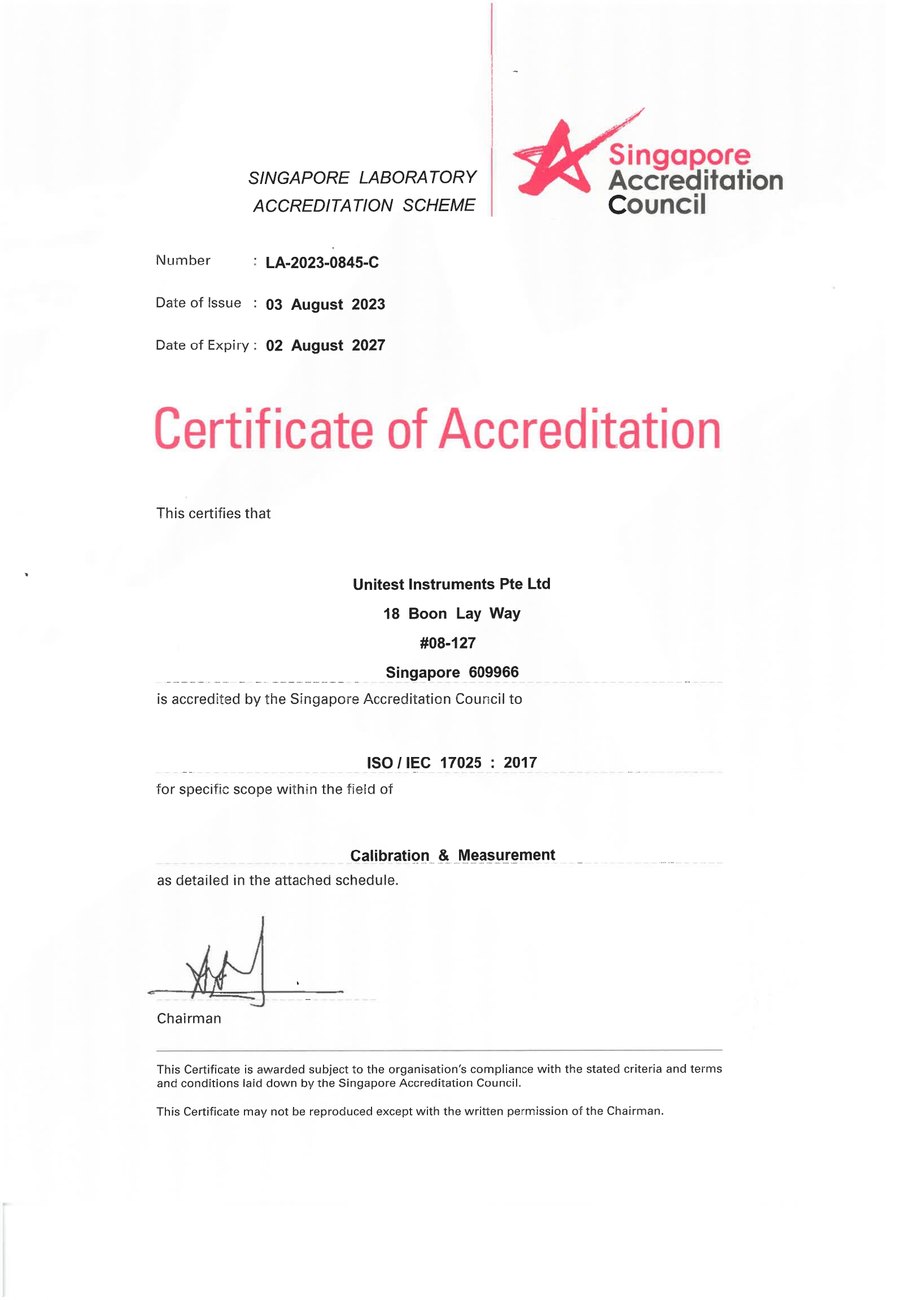
SAC-SINGLAS accredited calibration laboratory (Acc. No. LA-2023-0845-C) serving Singapore's industrial, pharmaceutical, and manufacturing sectors. All content reflects our ISO/IEC 17025 accredited scope and is reviewed by our technical calibration team.
Need ultrasonic thickness gauge calibration in Singapore?
Unitest Instruments is SAC-SINGLAS accredited (Acc. No. LA-2023-0845-C) to ISO/IEC 17025. Same-week turnaround, certificates accepted by ISO 9001 auditors and MOM Authorised Examiners.