
Key Takeaways
- PT100 RTDs cover −200 °C to +850 °C; NTC thermistors are practical only between −80 °C and +150 °C.
- IEC 60751 defines four RTD accuracy classes (AA, A, B, C); thermistors have no equivalent international interchangeability standard.
- Thermistors have 10× higher sensitivity (−3% to −6%/°C) than PT100s (0.385%/°C) but exhibit pronounced non-linearity.
- Self-heating error is a critical source of inaccuracy in both sensor types and must be quantified during calibration.
- RTDs cost more upfront but offer longer stability; thermistors are cheaper but require individual characterisation for high accuracy.
- Singapore's HSA and NEA regulations require traceable calibration. Only certificates from SAC-SINGLAS accredited labs are accepted by auditors.
What Are RTDs and Thermistors? Definitions and Core Distinctions
A Resistance Temperature Detector (RTD) is a passive sensor whose electrical resistance increases predictably with temperature. The most common variant is the PT100. A platinum element with a nominal resistance of 100 Ω at 0 °C. Platinum is chosen for its chemical stability, repeatability, and near-linear resistance–temperature relationship described by the Callendar–Van Dusen equation. The international standard governing PT100s is IEC 60751:2022 (equivalent to BS EN 60751 in the UK and ASTM E1137 in the United States), which specifies the R-T relationship, dimensional tolerances, and four accuracy classes.
A thermistor (a contraction of "thermal resistor") is a semiconductor-based sensor whose resistance changes non-linearly with temperature. Most thermistors used in measurement are NTC (Negative Temperature Coefficient) types (resistance falls as temperature rises), following the Steinhart–Hart equation: 1/T = A + B·ln(R) + C·(ln(R))³. A smaller category, PTC (Positive Temperature Coefficient) thermistors, are used primarily as resettable fuses and temperature switches, not precision sensors. There is no single international standard equivalent to IEC 60751 for thermistors; ASTM E879 provides guidance but does not define interchangeability classes.
The fundamental distinction is this: RTDs are linear, stable, and interchangeable; thermistors are sensitive, non-linear, and individually characterised. Both serve legitimate calibration and measurement roles, but only when matched correctly to the application.
Underlying Physics: Why Each Sensor Behaves as It Does
The Metal Conductor: RTD Physics
In a metallic conductor such as platinum, electrical resistance arises from the scattering of conduction electrons by the crystal lattice. As temperature increases, lattice vibrations (phonons) intensify, increasing scattering and therefore resistance. For platinum, this relationship is nearly linear between 0 °C and 850 °C, with a temperature coefficient of resistance (TCR) of approximately 0.00385 Ω/Ω/°C. Defined precisely by the α coefficient in IEC 60751. Below 0 °C, the relationship curves slightly, described by the Callendar–Van Dusen polynomial with coefficients A, B, and C.
The linearity of platinum means that a single two-point calibration (ice point and a reference temperature) can characterise the entire operating range within a known tolerance class. This is why PT100 RTDs from different manufacturers are interchangeable within IEC 60751 class tolerances. A critical advantage for regulated industries.
Semiconductor Thermistors: Exponential Sensitivity
NTC thermistors are made from metal oxide ceramics (typically mixtures of manganese, nickel, cobalt, or copper oxides). Their conduction mechanism is fundamentally different from metals: charge carriers (holes and electrons) are generated by thermal excitation across a semiconductor band gap. As temperature rises, more carriers are available, resistance falls exponentially. The simplified B-parameter model expresses this as: R(T) = R₀ · exp[B·(1/T − 1/T₀)], where B is the material constant (typically 2000–5000 K), T is absolute temperature in Kelvin, and R₀ is the resistance at reference temperature T₀ (usually 25 °C).
This exponential relationship produces a sensitivity of −3% to −6% per °C at room temperature. Roughly ten times greater than a PT100. However, the non-linearity means that a single B-parameter model introduces residual errors of up to 0.5 °C across a 100 °C span; the more precise Steinhart–Hart model with three coefficients (A, B, C) reduces this to less than 0.01 °C over a 50 °C range when coefficients are derived from individual calibration at three or more points.
Accuracy Classes, Standards, and Tolerance Figures
For RTDs, IEC 60751:2022 is the definitive reference. The four accuracy classes and their tolerances at 0 °C are:
| Accuracy Class | Tolerance Formula | Tolerance at 0 °C | Tolerance at 100 °C | Valid Range |
|---|---|---|---|---|
| Class AA | ±(0.1 + 0.0017|t|) °C | ±0.10 °C | ±0.27 °C | −50 °C to +250 °C |
| Class A | ±(0.15 + 0.002|t|) °C | ±0.15 °C | ±0.35 °C | −100 °C to +450 °C |
| Class B | ±(0.30 + 0.005|t|) °C | ±0.30 °C | ±0.80 °C | −196 °C to +600 °C |
| Class C | ±(0.60 + 0.010|t|) °C | ±0.60 °C | ±1.60 °C | −196 °C to +600 °C |
Note: |t| denotes the absolute value of temperature in degrees Celsius. Class AA applies only to thin-film elements or wire-wound elements meeting tighter geometric tolerances.
For thermistors, there is no IEC interchangeability class structure. Manufacturers publish individual accuracy specifications, commonly ±0.2 °C for standard grades and ±0.05 °C for high-accuracy interchangeable types over a specified range. The critical difference: a thermistor labelled "±0.1 °C" achieves that tolerance only in the specific range stated (e.g. 0 °C to 70 °C) and requires individual or batch calibration to maintain it. As noted in our article on measurement uncertainty in calibration, the tolerance stated on a sensor is not the same as its calibrated measurement uncertainty. The calibration certificate from an accredited laboratory is the authoritative source.
Temperature Range, Stability, and Long-Term Drift
The usable temperature range is one of the clearest differentiators between the two sensor types. PT100 RTDs per IEC 60751 are specified from −200 °C to +850 °C. In practice, wire-wound industrial RTDs are routinely used from −200 °C (cryogenic nitrogen) to +600 °C (furnace exhaust monitoring). Thin-film PT100s, while lower in cost, are typically limited to −50 °C to +500 °C due to substrate constraints.
NTC thermistors are practical between approximately −80 °C and +150 °C, with most commercial grades specified from −40 °C to +125 °C. Above 150 °C, the oxide semiconductor material begins to degrade irreversibly. Below −40 °C, resistance values climb into the megaohm range, making resistance measurement circuits impractical without specialised high-impedance electronics. PTC thermistors used as Curie-point switches have a much narrower transition range, making them unsuitable for precision measurement.
Long-term stability favours RTDs. Platinum is chemically inert and mechanically stable; a well-constructed PT100 probe in a clean environment drifts less than 0.05 °C per year. Industrial-grade NTC thermistors typically drift 0.1–0.2 °C per year under continuous use, with accelerated drift at high temperatures or in high-humidity environments. For process control in Singapore's equatorial climate (where ambient humidity regularly exceeds 80% RH), enclosure and seal quality is a critical factor in thermistor stability.
Need your RTDs or thermistors calibrated to traceable Singapore standards?
Unitest Instruments calibrates PT100 RTDs, NTC thermistors, and temperature transmitters from −196 °C to +1200 °C. Certificates accepted by ISO 9001, GMP, and HSA auditors.
Measurement Methods and Circuit Considerations
RTD Wiring Configurations
RTDs require an excitation current to generate a measurable voltage across the resistive element. The lead resistance in the connection wires between the sensor and the measurement instrument can introduce a systematic error, as high as 2–3 °C for a long 2-wire installation. Three wiring configurations address this:
- 2-wire: Simplest and least accurate. Lead resistance adds directly to the measured resistance. Acceptable only for short cable runs (<1 m) or where accuracy is non-critical.
- 3-wire: The most common industrial configuration. The third wire allows the instrument to compensate for lead resistance, providing good accuracy provided both measurement leads have equal resistance, typically true for factory-installed probes.
- 4-wire (Kelvin): The reference standard for laboratory and high-accuracy applications. Separate current-supply and voltage-sense leads completely eliminate lead resistance error. Required for Class AA calibration work and for resistance standard measurements.
Excitation current for PT100 RTDs is typically 1 mA, producing a 100 mV signal at 0 °C. This is easily measured by modern data loggers and transmitters. At 1 mA, the self-heating power in a PT100 element is P = I²R = 1 mW. Negligible in a stirred liquid bath but potentially several tenths of a degree in still air, depending on probe construction and thermal mass.
Thermistor Measurement Circuits
Thermistors are typically measured with excitation currents of 10 µA to 100 µA to limit self-heating. Because thermistor resistance spans several orders of magnitude (from a few ohms at high temperatures to several megaohms at low temperatures), the measurement circuit must accommodate a wide dynamic range. A simple voltage divider with a precision resistor is adequate for moderate accuracy; a ratio-metric Wheatstone bridge with a precision reference resistor provides higher accuracy and common-mode noise rejection.
The non-linearity of NTC thermistors means that direct analogue-to-digital conversion requires either hardware linearisation (a parallel resistor is sometimes used) or software linearisation using the Steinhart–Hart equation in the instrument firmware. Most modern temperature transmitters and data loggers include thermistor linearisation tables, but only for standard resistance–temperature curves. Custom or individually calibrated thermistors require the specific Steinhart–Hart coefficients from the calibration certificate to be entered into the instrument.
Calibration Implications for RTDs and Thermistors
Understanding how calibration differs between these sensor types is essential for laboratories, manufacturers, and regulated industries in Singapore. The article what every calibration certificate must contain covers the documentary requirements in detail; here we focus on the technical approach specific to temperature sensors.
RTD Calibration Approach
PT100 RTD calibration in an accredited laboratory follows a comparison method: the RTD under test is immersed alongside a reference Standard Platinum Resistance Thermometer (SPRT) or a calibrated secondary reference thermometer in a stirred liquid bath or dry-block calibrator. The bath temperature is stabilised at each calibration point (typically 5–7 points across the working range), and the RTD resistance is measured using a precision 4-wire bridge. The calibration report provides:
- Measured resistance at each calibration temperature
- Deviation from the nominal IEC 60751 R-T table in °C
- Expanded measurement uncertainty (k=2, 95% confidence) at each point
- The reference standard's traceability chain back to Singapore's NMC or an equivalent National Metrology Institute (NMI)
For critical applications, the calibration coefficients (corrected Callendar–Van Dusen coefficients) are provided, allowing the instrument to apply individual correction factors rather than using the nominal IEC 60751 table. This approach is standard practice in pharmaceutical qualification (GAMP 5) and in accordance with Singapore's Health Sciences Authority (HSA) Good Distribution Practice for medicinal products.
Thermistor Calibration Approach
Thermistor calibration follows the same comparison principle but requires at least three calibration points to determine the three Steinhart–Hart coefficients with sufficient accuracy. A single-point calibration can only verify conformance to a nominal resistance value; it cannot characterise the non-linearity. For pharmaceutical cold-chain applications (2 °C to 8 °C), thermistors are typically calibrated at four points: 0 °C, 4 °C, 8 °C, and 20 °C, providing coverage of the operating range plus a reference point for trend monitoring.
A key risk in thermistor calibration is drift between calibration events. Unlike platinum, metal oxide semiconductors can experience microstructural changes under thermal cycling, particularly at temperatures above 100 °C. For critical monitoring applications, annual calibration with a trend comparison to the previous certificate is best practice, any deviation exceeding 0.1 °C from the prior calibration warrants investigation before the device is returned to service.
Cost Comparison and Sensor Selection Guide
| Factor | PT100 RTD (Class B/A) | NTC Thermistor |
|---|---|---|
| Sensor element cost | S$15–S$150 (element); S$80–S$500+ (probe) | S$1–S$20 (bead/disc); S$30–S$200 (probe) |
| Calibration cost | Moderate; single-curve, 5–7 points | Higher per unit if individual Steinhart–Hart characterisation required |
| Interchangeability | Yes. IEC 60751 tolerance classes | No. Must match R-T curve to instrument configuration |
| Temperature range | −200 °C to +850 °C | −80 °C to +150 °C |
| Accuracy (typical) | ±0.1 °C to ±0.3 °C (class-dependent) | ±0.05 °C to ±0.2 °C (narrow range, characterised) |
| Sensitivity | 0.385 Ω/Ω/°C (linear) | −3% to −6%/°C (non-linear, exponential) |
| Long-term stability | Excellent (<0.05 °C/year) | Good (0.1–0.2 °C/year); degrades at high temp |
| Best application | Industrial process, calibration labs, wide range | Medical, HVAC, cold-chain, narrow-range precision |
The correct sensor choice depends on three decision criteria: temperature range, required accuracy, and regulatory context. For any application regulated by Singapore's HSA, NEA, or requiring ISO 9001 traceability, the calibration certificate is non-negotiable, and that certificate must come from a SAC-SINGLAS accredited laboratory. As detailed in our guide to accredited vs non-accredited calibration, certificates from non-accredited sources are routinely rejected by regulatory auditors and cannot be used to demonstrate metrological traceability to Singapore's National Metrology Centre.
Common Mistakes and How to Avoid Them
Several errors recur in RTD and thermistor applications in Singapore's manufacturing and pharmaceutical sectors:
- Using a 2-wire RTD without lead resistance compensation. In a facility where probe cables run 5–10 metres to a control panel, the lead resistance in a 2-wire circuit can introduce errors of 1–3 °C. Replace with 3-wire or 4-wire probes, or use a transmitter with built-in lead compensation.
- Swapping a thermistor without re-entering Steinhart–Hart coefficients. If a thermistor probe fails and is replaced with a physically identical unit, the instrument must be updated with the new unit's individual calibration coefficients. Assuming interchangeability is the most common cause of out-of-specification cold-chain readings post-maintenance.
- Ignoring self-heating in air measurements. Self-heating of 0.3–0.8 °C can occur when RTDs or thermistors are used in low-velocity air streams without appropriate excitation current control. Always verify self-heating contribution during calibration and document it in the uncertainty budget.
- Using dry-block calibrators without an external reference sensor. Dry-block calibrators have excellent repeatability but their displayed temperature can deviate from the insert bore temperature by 0.5–2 °C. Always use a calibrated reference probe in the reference hole and apply the correction. This is consistent with guidance in ISO/IEC 17025 calibration requirements.
- Exceeding the thermistor's maximum continuous temperature. Operating an NTC thermistor at 130 °C or above causes irreversible oxidation of the ceramic element. Resistance values will shift permanently, invalidating the calibration. Always verify the manufacturer's maximum operating temperature and design adequate thermal margins.
- Confusing tolerance class with calibrated uncertainty. A Class A RTD has a manufacturing tolerance of ±0.15 °C at 0 °C. This is a worst-case production specification, not a measurement uncertainty. After individual calibration, the same probe may be characterised to ±0.04 °C (k=2). The calibration certificate supersedes the class tolerance for metrological purposes.
Frequently Asked Questions
RTDs are generally more accurate over a wide temperature range. A Class AA PT100 RTD has a tolerance of ±(0.1 + 0.0017|t|) °C per IEC 60751, equating to roughly ±0.1 °C at 0 °C. NTC thermistors can achieve ±0.05 °C or better in a narrow range (typically 0 °C to 70 °C) when individually characterised, but their accuracy degrades rapidly outside that window and they are sensitive to self-heating errors at low excitation currents.
PT100 RTDs conforming to IEC 60751 cover −200 °C to +850 °C. Thermistors are limited to approximately −80 °C to +150 °C for NTC types; PTC thermistors typically operate from −55 °C to +125 °C. For cryogenic or high-temperature industrial applications above 200 °C, RTDs are the only practical resistive-sensor choice.
NTC thermistor resistance changes exponentially with temperature, following the Steinhart–Hart equation. A typical NTC thermistor has a sensitivity of −3% to −6% per °C at room temperature, compared with the linear 0.385% per °C of a PT100 RTD. This high sensitivity makes thermistors ideal for detecting small temperature changes in a narrow range, such as medical or HVAC applications, but the non-linearity demands careful signal processing and more calibration points.
Self-heating error occurs because both RTDs and thermistors require an excitation current to measure resistance, and that current dissipates power (P = I²R) as heat inside the sensor element. For a 100 Ω PT100 driven at 1 mA, the self-heating is 0.1 mW. Negligible in most liquids but significant in still air or low-conductivity media. Thermistors, with resistances of 2 kΩ to 100 kΩ, require far lower currents (typically 10–100 µA) to keep self-heating below 0.01 °C, complicating the measurement circuit design.
Calibration intervals depend on application criticality, operating conditions, and manufacturer recommendation. As a general guide, industrial PT100 RTDs in stable environments are calibrated every 12–24 months; thermistors used in medical or pharmaceutical cold-chain applications are often calibrated every 6–12 months due to drift concerns. ISO/IEC 17025 accredited laboratories such as Unitest Instruments can advise on risk-based interval setting in accordance with Singapore's regulatory requirements.
IEC 60751:2022 (identical to BS EN 60751) is the international standard for industrial platinum resistance thermometers (PRTs). It defines four accuracy classes: Class AA (±0.1 °C at 0 °C), Class A (±0.15 °C), Class B (±0.30 °C), and Class C (±0.60 °C), each expressed as a formula that accounts for both fixed and proportional errors across the sensor's operating range.
Yes, NTC thermistors are widely used in Singapore pharmaceutical cold-chain monitoring between 2 °C and 8 °C, where their high sensitivity (typically −4% per °C at 25 °C) provides excellent resolution. However, HSA Good Distribution Practice (GDP) requirements mandate that temperature monitoring devices be calibrated against traceable standards, which for Singapore means calibration by a SAC-SINGLAS accredited laboratory such as Unitest Instruments (Acc. No. LA-2023-0845-C).
Yes. Calibration certificates issued by a SAC-SINGLAS accredited laboratory under ISO/IEC 17025 provide metrological traceability to Singapore's National Metrology Centre (NMC) and are accepted by ISO 9001, GMP, HACCP, and HSA auditors. The certificate must include measurement uncertainty, reference standards used, and the accreditation number (LA-2023-0845-C for Unitest Instruments).
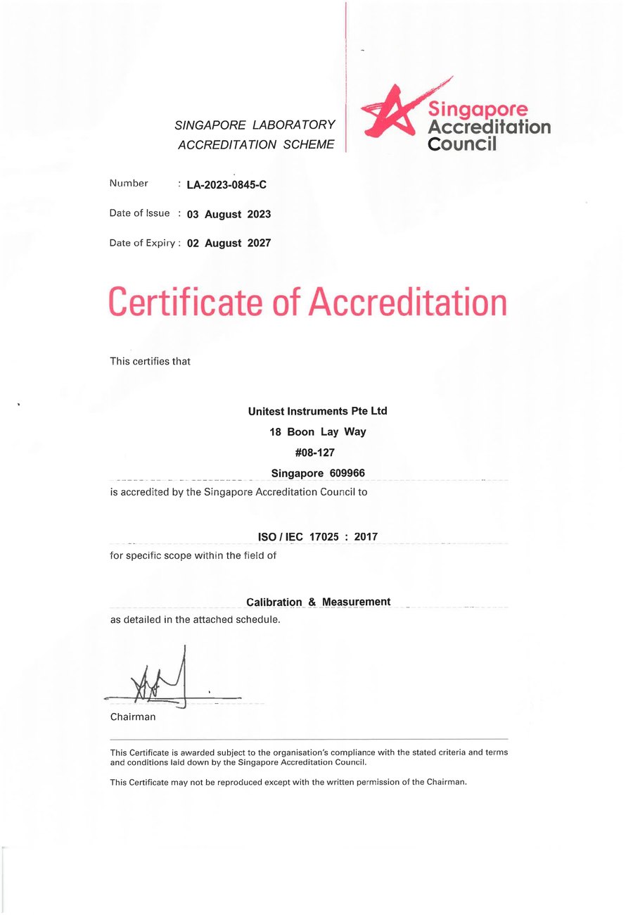
SAC-SINGLAS accredited calibration laboratory (Acc. No. LA-2023-0845-C) serving Singapore's industrial, pharmaceutical, and manufacturing sectors. All content reflects our ISO/IEC 17025 accredited scope and is reviewed by our technical calibration team.
Need temperature sensor calibration in Singapore?
Unitest Instruments is SAC-SINGLAS accredited (Acc. No. LA-2023-0845-C) to ISO/IEC 17025. Same-week turnaround, certificates accepted by ISO 9001 auditors.