
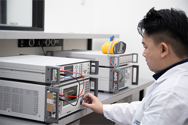
Key Takeaways
- The FEV500 completes the full CCS digital handshake (SLAC, then ISO 15118 or DIN SPEC 70121) itself, so a charger's communication stack can be verified without a real EV.
- It performs a real guided load test, drawing controlled DC current through the connector (up to 1000 V, 10 A, ~2 kW), not just a communication-only check.
- Electrical safety tests covered in the same sequence: insulation resistance (DC+ and DC- to PE), PE continuity, IMD no-trip/trip verification, and residual voltage after disconnection.
- Its rugged, wheeled, IP54 chassis with a removable Li-ion battery (up to 10 hours runtime) and 7-inch touchscreen is built for field use across a network of sites, not bench testing.
- Results are captured on-device and transferred via USB-C into Fluke TruTest™ software (PRO model) for reporting and documentation.
Why "no vehicle needed" is the whole point
Bringing a real electric vehicle to a charging site for testing sounds simple until you actually try to schedule it: a specific vehicle, a driver, a battery that has to be at the right state of charge to accept a meaningful test session, and a vehicle that may or may not even support the exact fault condition you are trying to reproduce. For charge point operators (CPOs) and service contractors responsible for keeping a network of DC fast chargers running, this is not a workable maintenance model, and it is a large part of why fast, repeatable field testing without a real vehicle has become essential capability rather than a nice-to-have. The Fluke FEV500 is built specifically to remove the vehicle from this equation, consolidating what would otherwise require an EV simulator, a CCS protocol analyzer, a low-ohm meter, an insulation tester, and an oscilloscope into a single rugged, wheeled, battery-powered instrument.
Step 1: completing the digital handshake
Before any DC power flows from a CCS2 charger, the charger and vehicle complete SLAC (Signal Level Attenuation Characterisation), a low-level pairing process over Power Line Communication (PLC) that establishes a secure digital link across the CCS connector's control pins. Once paired, the charger and vehicle negotiate the actual charging session under ISO 15118 (the current international standard, also used for features like Plug and Charge authentication) or the earlier DIN SPEC 70121 (still in use on some deployed infrastructure). The FEV500 performs this full exchange itself, including SLAC and PLC testing, so a fault that only manifests during pairing or negotiation, exactly the kind of issue that shows up as "works with some vehicles, not others" in the field, can be isolated and diagnosed without needing the specific vehicle model involved on site.
Step 2: a real load test, not just a communication check
Passing the digital handshake only confirms the charger and the analyzer can talk to each other; it does not confirm the charger's power electronics actually deliver correct, stable DC power. The FEV500's guided Autotest sequence goes further, drawing an actual controlled DC load, typically around 2 kW, through the CCS2 connector at voltages up to 1000 V and currents up to 10 A, and measuring the charger's actual voltage, current, and power output against what was requested during the digital negotiation. A charger that negotiates correctly but delivers the wrong voltage or an unstable current under load is a fault a communication-only test would miss entirely, and precisely what this step is designed to catch.
Step 3: electrical safety tests through the same connection
Alongside the load test, the FEV500 runs the DC-specific safety checks that a CCS2 charger requires, all through the same connector:
- Insulation resistance (RISO): DC+ to PE and DC- to PE separately, at a selectable 500 V or 1000 V test voltage, across a 10 kΩ to 20 MΩ range, per IEC 61557-2.
- PE continuity (RLO): using the supplied TP165X remote test probe, at test currents up to 10 A and 0.1 mΩ resolution, per IEC 61557-4.
- Insulation monitoring device (IMD) verification: both a no-trip test (confirming the IMD stays silent when insulation is healthy) and a trip test (confirming it correctly alarms when insulation is deliberately degraded), per IEC 61557-8.
- Residual voltage test: confirming that any residual charge on the DC conductors discharges to a safe level within the required time after the connector is disengaged, per IEC 61851-1's discharge requirements.
We cover why these specific tests exist, and how they differ from AC Mode 3 testing, in more depth in our AC vs DC fast charging comparison.
Step 4: error simulation for deeper diagnostics
Beyond a standard pass/fail sequence, the FEV500 can deliberately simulate charging states and fault conditions, verifying that the charger's own safety systems respond correctly when something goes wrong, rather than only confirming normal operation. Combined with waveform visibility into the communication exchange, this gives a technician a genuine diagnostic tool for intermittent or hard-to-reproduce faults, not just a go/no-go commissioning check.
| Spec | Fluke FEV500 |
|---|---|
| Connector | CCS2 (Combined Charging System) |
| Communication tested | ISO 15118 and DIN SPEC 70121, including SLAC and PLC |
| Load test | Up to 1000 V DC, 10 A, typ. 2 kW |
| Display | 7-inch capacitive touchscreen, 1024 x 600, up to 1,700 cd/m² (sunlight readable) |
| Battery | Removable Li-ion, 10.8 V / 6.8 Ah, up to 10 hours runtime, ~3 hr recharge via 65 W USB-C PD |
| Ingress protection | IP54 (lid closed), per IEC 60529 |
| Dimensions / weight | 650 x 508 x 300 mm / 26 kg, rugged wheeled chassis |
| Operating temperature | -20°C to 50°C |
| Warranty | 2 years |
Test your CCS2 fast chargers without waiting for a vehicle
Unitest Instruments is an authorised Fluke distributor supplying the FEV500 for commissioning, periodic inspection, and fault diagnosis of DC fast charging stations, backed by our SAC-SINGLAS accredited calibration lab.
Reporting: from the connector to a finished record
Results captured during the Autotest sequence are recorded directly on the FEV500's touchscreen and transferred via USB-C into Fluke's TruTest™ data management and reporting software (included with the PRO model), turning a field test session into a documented, retrievable maintenance or commissioning record without a technician manually transcribing readings. Where the FEV500 is used as part of a full commissioning sequence, our EVSE commissioning checklist for Singapore sets out where this step fits alongside the rest of the required documentation.
The real operational problem this instrument solves
Before instruments like the FEV500 existed, verifying a DC fast charger's full functionality genuinely required a compatible electric vehicle physically present at the charging bay, and this created a scheduling constraint that most charge point operators and testing contractors found surprisingly limiting in practice. A commissioning technician needing to test 15 chargers across a distributed network in a single day cannot realistically coordinate borrowing a specific EV model for each site, particularly where the goal is testing against several different vehicle communication implementations rather than just one. A fleet operator wanting to run a scheduled maintenance verification overnight, when no vehicles are available to plug in, previously had no way to confirm a charger's communication and load-handling functions at all outside of live customer sessions, meaning faults could only be caught reactively, after a driver reported a failed charging attempt. Removing the dependency on a physically present vehicle converts EV charger testing from an opportunistic, vehicle-availability-constrained activity into a schedulable, repeatable maintenance task that a testing contractor or facilities team can plan and budget for like any other periodic inspection.
What a load box test verifies and what it cannot substitute for
It is worth being precise about what "testing without an EV" actually verifies versus what it does not. The FEV500 completes the genuine ISO 15118 or DIN SPEC 70121 digital handshake and draws real current through a load bank up to its rated 1000 V / 10 A, so the charger's communication stack, power delivery control, and protective functions are all genuinely exercised, not simulated in software. What it does not replicate is the exact communication implementation quirks of every individual vehicle manufacturer's onboard charging controller; different EV models occasionally implement edge cases of the ISO 15118 or DIN SPEC 70121 standards with slight variations, and a charger that passes cleanly against the FEV500's standards-compliant test sequence could, in rare cases, still encounter an interoperability issue with one specific vehicle model's particular implementation quirk. This is not a flaw in the test methodology, a load box testing against the published standard is testing what the charger is actually required to support, but it explains why, even after a charger passes its full FEV500 Autotest sequence, an occasional vehicle-specific compatibility report can still surface in the field, and why maintaining a record of which vehicle models have reported issues at which sites remains a useful supplementary practice for a CPO operating a large public network.
Comparing this approach to a real-vehicle acceptance test
Some commissioning specifications, particularly for high-profile public charging sites or where a specific fleet operator's vehicle is the primary intended user, still call for a final real-vehicle acceptance test alongside the instrumented Autotest sequence. Where this is required, the practical sequence most testing contractors follow is to run the full FEV500 test first, resolving any communication, load, or safety fault while the site is already mobilised for testing, and only bring in a real vehicle for a final confirmation session once the instrumented test has passed cleanly. This ordering avoids the far more expensive and time-consuming alternative of discovering a basic communication or safety fault only once a real vehicle is already on-site, at which point diagnosing the root cause without the FEV500's waveform visibility and error simulation capability is considerably harder. Treating the real-vehicle test as a final confirmation step rather than the primary diagnostic tool is generally the more efficient sequencing for both cost and technician time.
Deciding when a vehicle-specific compatibility report warrants investigation
When a driver reports a compatibility issue with a specific vehicle model at a charger that has already passed its full FEV500 test sequence, the practical question is when this warrants further investigation versus being logged as a known, low-priority compatibility note. A single isolated report from one vehicle at one site, where the charger otherwise passes its standards-compliant test and serves other vehicle models without issue, is reasonably treated as a documented compatibility note rather than an active fault requiring immediate escalation. A pattern of the same vehicle model reporting the same issue across multiple different chargers and sites is a stronger signal worth escalating to the vehicle manufacturer directly, since it suggests the issue sits in that vehicle's own onboard charging controller implementation rather than being specific to any one installation. And a charger showing the issue with multiple different vehicle models, not just one, despite having passed its FEV500 test, is the pattern that warrants re-testing the charger itself and reviewing whether its firmware or configuration has changed since the original commissioning test, since this pattern points toward the charger rather than any individual vehicle's implementation quirk. Building this kind of simple triage logic into a CPO's fault-handling process avoids both under-reacting to a genuine emerging charger fault and over-reacting to an isolated, low-consequence vehicle compatibility quirk.
Battery runtime and field-day planning for busy testing schedules
The FEV500's removable battery, rated for up to 10 hours of runtime, is specifically sized around a realistic field testing day, but planning a multi-site commissioning or maintenance schedule still benefits from understanding what actually consumes battery capacity during a working day. A full Autotest sequence including the digital handshake, sustained load test, and DC insulation checks draws meaningfully more current than the instrument sitting idle between tests, so a busy day involving many consecutive full test sequences, rather than occasional spot checks, will draw down the battery faster than the rated runtime figure alone might suggest for casual use. For testing contractors covering multiple sites in a single day, carrying a charged spare battery (the FEV500's removable design specifically supports this) or planning charging windows during site-to-site travel avoids the scenario of a battery running low midway through the day's final site, a scenario more disruptive during instrumented commissioning work than for many other test instruments given how central the FEV500 is to actually completing a DC fast charger's test sequence at all.
Calibration of the FEV500 itself
The FEV500 is a precision test instrument in its own right, its voltage and current measurement functions, and the accuracy of the load it presents during a load test, need to be periodically verified against a traceable reference just like any other electrical test instrument, following the same principles covered in our guide to EV charging test equipment calibration in Singapore. An uncalibrated FEV500 producing a "pass" result carries the same weakness as any other uncalibrated instrument: the pass result is only as trustworthy as the instrument's own last verified accuracy. For a testing contractor or CPO whose commissioning and maintenance records feed into a customer's own quality system, or into an ISO 9001-certified operation, keeping the FEV500 itself on a documented annual calibration interval, with a certificate stating measurement uncertainty and traceability, closes the same evidentiary gap that any other uncalibrated test instrument would leave open.
Software and firmware updates: keeping pace with a moving standard
ISO 15118 and DIN SPEC 70121 are living standards, with vehicle manufacturers and charger manufacturers continuing to refine their implementations over time, which means the FEV500's own software and firmware are periodically updated by Fluke to maintain accurate testing against current implementations in the field. Running an outdated software version on the FEV500 risks two distinct problems: failing to correctly test against a newer vehicle communication implementation the software has not yet been updated to recognise, or, less obviously, passing a charger against an older standard interpretation that a newer vehicle no longer strictly follows. For a testing contractor or CPO relying on the FEV500 as the primary verification tool for DC fast charging compliance, keeping the instrument's software current, checking for and applying updates on a regular schedule rather than only when a specific testing problem prompts investigation, is a genuinely practical maintenance task that sits alongside, but is distinct from, the instrument's own electrical calibration discussed above. Both together, current software and current calibration, are what keep the FEV500's "pass" result meaningful against the actual current state of the standards and vehicles it is testing against.
Documenting software version alongside test results
Because the underlying communication standards continue to evolve, a genuinely complete commissioning or maintenance record for a DC fast charger should note which FEV500 software version was in use at the time of testing, not just the pass/fail result itself. This matters practically if a compatibility question is ever raised months or years later about a specific vehicle model: knowing which software version tested the charger at commissioning lets a facilities team or testing contractor establish whether a newer vehicle's reported issue reflects a genuine charger fault, or simply reflects a vehicle communication implementation that postdates the software version used at the original test. Fluke's TruTest reporting typically captures this software version detail automatically as part of the generated report, which is one further practical reason to rely on the structured reporting workflow rather than manually transcribed results, where this kind of contextual detail is easy to omit.
Frequently Asked Questions
It completes the same digital handshake a real vehicle would (SLAC pairing, then ISO 15118 or DIN SPEC 70121 negotiation) and then draws a real controlled DC load through the CCS2 connector, so the charger's full communication and power delivery sequence is exercised exactly as it would be with a genuine vehicle connected, without one actually being present.
The FEV500's guided load test draws a controlled DC load up to 1000 V and 10 A, with typical load power around 2 kW, sufficient to verify the charger's power stage delivers correct voltage, current and power under a real, known load condition.
Yes. The FEV500 supports full charging communication testing to both ISO 15118 (the current international standard) and the earlier DIN SPEC 70121, including SLAC and Power Line Communication (PLC) testing, covering both currently deployed protocol generations.
It runs insulation resistance testing on DC+ and DC- conductors separately (500 V / 1000 V, per IEC 61557-2), PE continuity testing via a remote test probe (per IEC 61557-4), insulation monitoring device no-trip and trip verification (per IEC 61557-8), and a residual voltage test after the connector is disengaged.
Field use. It has a rugged wheeled chassis, a removable lithium-ion battery rated for up to 10 hours of runtime, an IP54 rating (lid closed), a sunlight-readable 7-inch touchscreen, and an operating temperature range of -20°C to 50°C, all reflecting its role travelling between charging sites rather than sitting on a workbench.
Yes. Beyond its standard Autotest sequence, the FEV500 can deliberately simulate charging states and fault conditions to verify the charger's own safety systems respond correctly, with waveform visibility into the communication exchange, giving a technician a genuine diagnostic capability for intermittent or hard-to-reproduce faults.
Results are captured directly on the FEV500's touchscreen during the test and transferred via USB-C into Fluke's TruTest™ data management and reporting software (included with the PRO model), producing a documented maintenance or commissioning record without manual transcription.

Unitest Instruments Pte. Ltd. is a SAC-SINGLAS accredited calibration laboratory (ISO/IEC 17025, Lab No. LA-2023-0845-C) and an authorised Fluke distributor in Singapore. We supply and calibrate test & measurement instruments, including the Fluke E-Mobility range, for EVSE installers, facilities managers, and charge point operators.
Keep your DC fast charging network running without waiting on a spare EV
Unitest Instruments is an authorised Fluke distributor for the FEV500 in Singapore, backed by our SAC-SINGLAS accredited (Acc. No. LA-2023-0845-C) calibration lab.
SAC-SINGLAS accredited · ISO/IEC 17025 · Authorised Fluke distributor