
Key Takeaways
- Traceability means every RF reference standard links back to a National Metrology Institute through an unbroken chain of calibrations, each with stated uncertainty.
- A calibration kit's open, short, load, and thru (OSLT) standards let a network analyzer mathematically remove its own systematic error at the measurement reference plane.
- Mismatch uncertainty (caused by impedance imperfections at every connector interface), is typically one of the largest contributors to RF measurement uncertainty.
- RF uncertainty is evaluated using the ISO GUM framework, combining Type A (statistical) and Type B (other-evidence) uncertainty contributors into a single expanded uncertainty.
- Frequency references such as rubidium or GPS-disciplined oscillators anchor frequency accuracy verification for signal generators and spectrum analyzers.
Traceability: The Foundation of RF Calibration
Every measurement result an accredited RF calibration laboratory issues rests on a chain of traceability. An unbroken sequence of calibrations, each performed against a higher-level reference standard with a documented measurement uncertainty, ultimately connecting back to a National Metrology Institute. In Singapore, that institute is the National Metrology Centre (NMC), operating under the Agency for Science, Technology and Research (A*STAR). This chain is what allows a calibration certificate issued in a commercial laboratory to carry real evidentiary weight in a quality system, a regulatory submission, or a customer audit: the number on the certificate is not just "close to correct," it is demonstrably linked, with a known uncertainty at each link, to an internationally recognised standard.
For RF and microwave work specifically, the quantities that need to be traceable include frequency, RF power, and (for network analyzer work), the complex ratio and phase relationship that make up S-parameters (scattering parameters). Each of these requires its own reference standard and its own traceability path, which is one reason RF calibration laboratories maintain a more elaborate reference standard inventory than a general electrical calibration lab.
Reference Standards Used in RF Metrology
Frequency References
Frequency accuracy verification for signal generators and spectrum analyzers depends on a stable frequency reference. Most accredited RF laboratories use a rubidium atomic frequency standard or a GPS-disciplined oscillator (GPSDO) as their day-to-day working reference, both of which achieve very low frequency uncertainty and excellent long-term stability compared with a simple crystal oscillator. The working reference is itself periodically calibrated against a primary time-and-frequency standard, closing the traceability chain.
Power References
RF power measurement accuracy is verified using a calibrated power sensor together with a stable power reference source. Because power sensor response can vary with frequency, calibration is generally performed at several frequency points across the sensor's specified range, with the reference source's absolute power level itself traceable to a national power standard.
Calibration Kits: Open, Short, Load, and Thru
Vector network analyzer (VNA) calibration is conceptually different from calibrating a signal generator or power meter, because a VNA does not simply display a value to compare against a reference. It needs to be mathematically corrected at its own measurement reference plane before it can accurately characterise anything connected to it. This is done using a precision calibration kit containing four standard elements, commonly abbreviated OSLT:
- Open. A standard presenting a known, near-total reflection with a defined phase behaviour.
- Short. A standard presenting a known, near-total reflection with the opposite phase sense to the open.
- Load. A standard presenting a matched termination (ideally the system's characteristic impedance, typically 50 Ω) that absorbs the signal with minimal reflection.
- Thru. A standard that connects two measurement ports directly together with a known, well-characterised transmission response.
By measuring all four standards at the reference plane, the VNA's internal calibration software solves for the systematic error terms contributed by the analyzer's own signal paths and the connecting cables, then mathematically removes them from subsequent measurements. This is what allows a network analyzer to report the true S-parameters of a device under test (filter, amplifier, antenna, or cable assembly), rather than a result contaminated by the test setup itself. The calibration kit's own standards must themselves be characterised and traceable, since any error in their known values propagates directly into every measurement made after the VNA calibration.
| Standard Element | Nominal Behaviour | Role in VNA Calibration |
|---|---|---|
| Open | Near-total reflection, defined phase | Characterises directivity/reflection error terms |
| Short | Near-total reflection, opposite phase to open | Complements open for reflection error correction |
| Load | Matched termination, minimal reflection | Establishes the reference impedance (commonly 50 Ω) |
| Thru | Direct, known transmission path | Characterises transmission/tracking error terms |
Need a network analyzer, signal generator, or power meter calibrated with full traceability?
Unitest Instruments issues RF calibration certificates with documented uncertainty budgets, traceable to Singapore's NMC and accepted by ISO 9001 auditors.
Mismatch Uncertainty: The Contributor Engineers Underestimate
Mismatch uncertainty arises whenever the impedance of a source, a cable, or a load is not perfectly equal to the system's characteristic impedance. Most commonly 50 Ω in general-purpose RF test equipment. At every interface where impedance is imperfectly matched, part of the signal reflects instead of continuing forward. Because two or more reflections in a signal chain can add constructively or destructively depending on the exact cable length and frequency, mismatch uncertainty behaves differently from a typical additive error: it is usually expressed as a bounded range (a maximum possible effect) rather than a single, precisely known value, and modelled with a U-shaped probability distribution reflecting that the true error is more likely to be near the bounds than at zero.
In practice, mismatch uncertainty is frequently one of the largest single contributors to the overall uncertainty budget in RF power measurement and network analyzer work. Often larger than the stated uncertainty of the reference standard itself. This is why accredited RF laboratories characterise the reflection coefficient (or voltage standing wave ratio, VSWR) of their reference standards, cables, and connecting hardware, and factor that data explicitly into the uncertainty calculation for every RF calibration they issue.
How Uncertainty Is Calculated: The GUM Framework
RF measurement uncertainty, like uncertainty in any accredited calibration discipline, is evaluated using the framework set out in ISO/IEC Guide 98-3, commonly known as the GUM (Guide to the Expression of Uncertainty in Measurement). Under this framework, each individual source of uncertainty in a calibration. The reference standard's own calibration uncertainty, mismatch uncertainty, connector repeatability, instrument resolution, and environmental effects. Is evaluated as either:
- Type A. Evaluated statistically from a series of repeated measurements, using the standard deviation of the observed results.
- Type B. Evaluated from other available information, such as a reference standard's calibration certificate, a manufacturer's specification, or published data on a known effect like mismatch.
These individual contributors are combined (typically by root-sum-of-squares, weighted by sensitivity coefficients) into a combined standard uncertainty, then multiplied by a coverage factor (commonly k = 2, giving approximately 95% confidence), to produce the expanded uncertainty reported on the calibration certificate. For a deeper walkthrough of this process, see our guide on Type A vs Type B uncertainty and our practical guide to building a calibration uncertainty budget.
General Alignment with IEEE and IEC Practice
RF and microwave metrology practice broadly follows guidance aligned with IEEE and IEC standards covering electronic test instrumentation and RF measurement methods, layered on top of the general uncertainty framework in ISO/IEC Guide 98-3. Rather than a single governing document, accredited RF laboratories typically build validated procedures from a combination of instrument manufacturers' calibration guides, relevant general test-instrument standards, and their own in-house method validation. All of which is independently assessed as part of ISO/IEC 17025 accreditation. This is why the scope of accreditation matters: a laboratory's accredited scope specifically listing RF or microwave calibration capability is the clearest evidence that its procedures, reference standards, and uncertainty analysis for this discipline have been independently reviewed.
Vector Network Analyzer calibration: SOLT versus TRL
Vector Network Analyzers (VNAs), used to measure S-parameters (reflection and transmission) of RF components and circuits, are calibrated using a fundamentally different method from simpler RF instruments: rather than comparing a single reading against a single reference value, VNA calibration characterises and mathematically removes the systematic errors of the entire measurement system, cables, connectors, and internal instrument imperfections included, using a defined set of known reference standards. SOLT (Short-Open-Load-Thru) calibration uses four well-characterised standards connected in sequence to build an error model covering the full measurement path, and is the most widely used method for general-purpose VNA work given the wide availability of SOLT calibration kits across common connector types. TRL (Thru-Reflect-Line) calibration, using a thru connection, a reflective standard, and a precision transmission line, achieves higher accuracy in specific applications, particularly non-coaxial environments like on-wafer or fixture-based measurement, where ideal SOLT standards are difficult to realise physically. Neither method is universally superior; the choice depends on the connector or measurement environment, the accuracy required, and what standards are practically available, and a competent RF lab selects the method matched to the actual measurement being performed rather than defaulting to one method regardless of application.
Frequency counters and power meters: simpler methods, still real error sources
Not every RF calibration involves the full complexity of VNA error correction. Frequency counters are calibrated by comparing their reading against a traceable frequency reference (a caesium or rubidium-disciplined standard, or a GPS-disciplined reference locked ultimately to a national timing standard), across the counter's specified frequency range, with the reference's own stability being the dominant factor in achievable calibration uncertainty. Power meters are calibrated using a calibrated power reference source, typically at a defined power level and frequency, verifying the meter's reading against a known input power, with the power sensor's own cable and connector condition significantly affecting the result, since a worn or damaged connector interface introduces exactly the kind of reflection-driven mismatch error discussed above. Both instrument types are conceptually simpler to calibrate than a VNA, but neither is immune to the underlying RF measurement error sources, connector condition, cable quality, and reference stability, that run through every method covered in this guide.
Mechanical versus electronic calibration kits
Traditional mechanical calibration kits (a physical set of short, open, load, and thru standards connected by hand in sequence) remain widely used and, when well maintained, achieve excellent accuracy, but they depend on consistent, careful technique from the technician performing the calibration, since each connection introduces its own small variability. Electronic calibration (ECal) modules, a single unit containing electronically switched internal standards, automate this process, reducing operator-dependent variability and significantly speeding up the calibration procedure, at a higher upfront cost than a mechanical kit. Both kit types require their own periodic recalibration against a higher-tier reference to remain valid, and this is a detail worth confirming with any RF calibration provider: an ECal module or mechanical standard kit that is itself overdue for recalibration undermines the accuracy of every measurement calibrated using it, in exactly the same way an out-of-calibration reference standard undermines any other discipline's calibration chain.
Connector care and gauging: a discipline that protects the whole calibration chain
RF connectors are precision mechanical interfaces, not simple electrical contacts, and their physical condition directly determines both the accuracy achievable in any measurement made through them and the risk of damaging expensive reference standards or the instrument itself. Connector pin depth, whether the centre pin sits at the correct protrusion or recession relative to the connector's mating plane, is checked using a dedicated pin depth gauge before connecting to a sensitive reference standard, since a pin protruding too far can physically damage the mating connector on contact, an expensive and avoidable failure mode entirely preventable through routine gauging discipline. Correct mating torque, applied using a calibrated RF torque wrench specific to the connector type (SMA, N-type, and 3.5mm connectors each specify different torque values), ensures a repeatable, low-reflection connection without over-tightening, which can damage the connector's precision mating surfaces over repeated use. Accredited RF laboratories build this connector care discipline into their standard operating procedure precisely because a single damaged connector, whether on a customer's instrument or the lab's own reference standards, can silently degrade every subsequent measurement made through it until the damage is eventually noticed, often only once results start looking anomalous.
Cable and adapter effects: often overlooked, always present
Every cable and adapter inserted between an instrument and the device under test introduces its own insertion loss, phase shift, and potential mismatch, and while a full VNA calibration (SOLT or TRL, as discussed above) mathematically removes these effects for measurements made at the calibration reference plane, any cable or adapter inserted after that calibration point reintroduces uncorrected error. This is a common practical mistake even among experienced RF technicians: calibrating a VNA at the end of a test cable, then inserting an additional adapter to connect to the actual device under test, without extending the calibration reference plane to account for that adapter's own effects. For simpler instruments like power meters and signal generators outside a full VNA calibration workflow, cable and adapter loss must be measured or estimated separately and accounted for in the overall measurement uncertainty budget, since the instrument's own calibration certificate says nothing about the loss introduced by whatever cable happens to connect it to the device actually being tested. Building awareness of this cable and adapter effect into a technician's standard measurement practice, not just into the formal calibration procedure itself, is what prevents a genuinely well-calibrated instrument from still producing a misleading result in practice.
Reading an RF calibration certificate: what genuinely competent uncertainty reporting looks like
A properly built RF calibration certificate, reflecting the methods and error sources covered throughout this guide, states more than a single pass/fail line per frequency point. It should show the measured value, the reference value applied, the deviation between them, and an expanded uncertainty that specifically accounts for the dominant RF-specific error sources relevant to that measurement: mismatch uncertainty where impedance mismatch is a genuine factor, the reference standard's own calibration uncertainty, and, for VNA-based measurements, the residual error terms remaining after the SOLT or TRL correction was applied. A certificate that states only a bare pass/fail with no supporting uncertainty breakdown, particularly for higher-frequency or vector measurements where mismatch uncertainty can be a genuinely significant contributor, is providing considerably less assurance than one built on the fuller GUM-based uncertainty analysis this guide has described, even where both nominally carry the same accreditation logo.
Putting it together: RF calibration as an engineering discipline, not a formality
The overarching point running through this guide is that RF calibration is a genuinely more involved technical discipline than general electrical calibration, given the additional physics (mismatch, connector condition, cable and adapter effects, and the specialised error-correction mathematics behind VNA calibration) that simply do not arise in DC or low-frequency electrical measurement. Treating RF calibration as a routine, interchangeable service commodity, rather than a discipline requiring genuine specialist competence from the provider and genuine specialist awareness from the equipment owner, is where measurement quality quietly erodes across many organisations relying on RF test equipment. The practical takeaway for any organisation depending on accurate RF measurement, across the industries covered in our companion guide to RF calibration industry applications, is to engage with a calibration provider genuinely capable of explaining the methods behind their certificates, not merely one able to produce a certificate that looks complete on its surface.
Why This Matters for Equipment Owners
Understanding the standards and methods behind RF calibration helps equipment owners ask better questions of their calibration provider, whether the uncertainty budget accounts for mismatch, whether the calibration kit standards are themselves traceable and within their own calibration interval, and whether the frequency and power references used are appropriate for the instrument's specified accuracy. A calibration certificate that simply states "calibrated" without this supporting rigor provides far less assurance than one built on a properly documented traceability chain and uncertainty budget.
Frequently Asked Questions
Traceability in RF calibration means that the value assigned to a measurement (frequency, power, or an S-parameter), can be linked through an unbroken chain of calibrations, each with a stated measurement uncertainty, back to a National Metrology Institute. In Singapore, this chain leads to the National Metrology Centre (NMC) under A*STAR. Every reference standard used in an accredited RF calibration must itself carry a current calibration certificate showing this chain.
Open, short, load, and thru (often abbreviated OSLT) are the four standard elements in a typical RF calibration kit used to calibrate a vector network analyzer at its measurement reference plane. The open and short standards present known, well-characterised reflection conditions, the load standard presents a matched termination with minimal reflection, and the thru standard connects two ports directly together. Measuring all four allows the VNA's internal software to mathematically remove the systematic errors of the analyzer and its cables, so later measurements reflect the true behaviour of the device under test.
Mismatch uncertainty is the measurement error that arises when the impedance of a source, a connecting cable, and a load are not perfectly equal, causing part of the RF signal to reflect at each interface instead of being fully absorbed or transmitted. Because these reflections can add constructively or destructively depending on cable length and frequency, mismatch uncertainty is usually expressed as a bounded range rather than a single value, and it tends to be one of the largest contributors to overall uncertainty in power and network analyzer measurements.
RF measurement uncertainty is evaluated following the general framework in ISO/IEC Guide 98-3, the Guide to the Expression of Uncertainty in Measurement (GUM). Individual uncertainty contributors. Such as the reference standard's own uncertainty, mismatch uncertainty, cable and connector repeatability, and instrument resolution. Are each characterised as Type A (evaluated statistically from repeated measurements) or Type B (evaluated from other information such as a calibration certificate or manufacturer specification), then combined into a single expanded uncertainty figure reported on the calibration certificate.
Accredited RF laboratories typically use a rubidium atomic frequency standard or a GPS-disciplined oscillator as their working frequency reference, both of which offer very low frequency uncertainty and long-term stability. This reference is used to verify the frequency accuracy of signal generators and spectrum analyzers, and its own calibration is traceable to a National Metrology Institute's time and frequency standard.
RF and microwave metrology practice broadly aligns with IEEE and IEC standards covering electronic test instrumentation and measurement methods, alongside the general measurement uncertainty framework in ISO/IEC Guide 98-3. Accredited laboratories build validated in-house procedures from a combination of instrument manufacturer calibration guidance, relevant general test-instrument standards, and their own method validation, all of which is assessed during ISO/IEC 17025 accreditation.
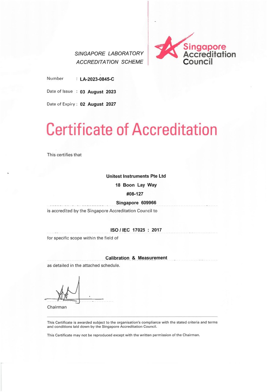
SAC-SINGLAS accredited calibration laboratory (Acc. No. LA-2023-0845-C) serving Singapore's industrial, telecom, and manufacturing sectors. All content reflects our ISO/IEC 17025 accredited scope and is reviewed by our technical calibration team.
Need traceable RF calibration standards applied to your equipment?
Unitest Instruments is SAC-SINGLAS accredited (Acc. No. LA-2023-0845-C) to ISO/IEC 17025. Documented uncertainty budgets on every certificate.