
Key Takeaways
- Connectors must be torqued to the manufacturer's specified value with a calibrated torque wrench. Hand-tight or over-torqued connections both introduce measurement error.
- Moving or flexing cables after calibration changes their electrical length and can shift phase/amplitude readings, especially at microwave frequencies.
- Mismatch uncertainty from imperfect impedance matches between connectors and cables is frequently one of the largest contributors in an RF uncertainty budget and must be calculated, not assumed away.
- Verifying only a handful of frequency points instead of a full sweep across the instrument's operating range can hide out-of-tolerance behaviour at untested frequencies.
- An internal self-calibration or auto-alignment routine is not a substitute for a traceable, accredited external calibration. It corrects drift but does not establish traceability to a National Metrology Institute.
Why RF Calibration Is More Error-Prone Than DC or Low-Frequency Work
At DC and low audio frequencies, a connection is largely binary. It is either making electrical contact or it isn't. At radio and microwave frequencies, a connection is a distributed electrical structure in its own right. The physical geometry of a connector interface, the exact torque applied, the electrical length of a cable, and even the temperature of the dielectric inside a coaxial line all become part of the measurement. This is why RF and microwave calibration workflows are far less forgiving of the small shortcuts that would be harmless in a DC multimeter calibration.
Signal generators, spectrum analysers, network analysers, and power meters used in telecom, semiconductor test, and defence-related RF work all depend on this chain of physical connections being controlled and repeatable. A calibration that does not account for connector condition, cable stability, mismatch, and temperature is not fully characterising the instrument's real-world performance. It is only checking that the instrument functions under one narrow, best-case condition.
The errors covered in this article are drawn from patterns that recur across accredited RF calibration practice generally, not any single laboratory's specific incident history, and they share a common thread: each one is individually small, individually plausible to dismiss as "close enough," and individually capable of hiding behind a certificate that otherwise looks entirely professional. It is the accumulation and interaction of several of these errors together, rather than any single dramatic mistake, that most often explains why an instrument that "should have been fine" produces measurably wrong results in the field months after a calibration that appeared to pass without issue.
Error 1: Incorrect Connector Torque
Every precision RF connector type (N-type, SMA, 3.5 mm, 2.92 mm, 2.4 mm), has a manufacturer-specified torque value for making up the connection. This value exists because the connector's mating pins need a consistent, repeatable contact pressure to present a stable, low-reflection interface. Hand-tightening "until it feels snug" produces a different contact pressure every time, which shows up as run-to-run variation in return loss and insertion loss that has nothing to do with the device under test.
Over-torquing is just as damaging, and arguably worse because the damage is often permanent. Excess torque can deform the center pin, crush the dielectric bead, or distort the outer conductor threads, degrading the connector's performance for the rest of its working life and potentially damaging the mating connector on an expensive instrument. A calibrated torque wrench, sized to the connector type, removes this variable from the measurement entirely and should be considered mandatory equipment for any RF calibration bench.
| Connector Type | Typical Torque Range | Common Failure Mode |
|---|---|---|
| 2.4 mm / 2.92 mm | Low torque, precision wrench required | Pin damage from over-torque; loose contact from under-torque |
| 3.5 mm | Moderate torque, precision wrench required | Thread wear from repeated over-tightening |
| SMA | Moderate torque | Cross-threading if hand-started incorrectly |
| N-type | Higher torque than SMA | Under-torque causing intermittent contact and elevated VSWR |
Exact torque values vary by manufacturer and connector generation and should always be taken from the connector or instrument manufacturer's specification rather than assumed from a general table.
Error 2: Cable Flexure and Repeatability Error
A test cable calibrated in one physical position and then flexed, coiled, or re-routed before the measurement is taken will not present exactly the same electrical length or impedance profile it had during calibration. This is known as cable flexure error or cable stability error, and it is one of the most under-appreciated sources of measurement uncertainty in RF test setups, particularly with lower-cost flexible cables.
At microwave frequencies, a wavelength can be a matter of millimetres or centimetres, so a small physical movement of a cable represents a non-trivial fraction of a wavelength. Enough to produce a measurable shift in phase and amplitude response. The practical fix is straightforward: fix cable routing and position before calibrating, avoid touching or repositioning cables between calibration and measurement, and where the setup must be moved, use phase-stable, low-flexure-loss cable assemblies designed for that purpose.
Practical Discipline on the Bench
Many labs address flexure error procedurally rather than only with better cable. Securing cables to the bench with strain relief, labelling cable position, and re-verifying a reference measurement any time a cable has been disturbed. This is a low-cost control that closes a real gap between "calibrated on paper" and "performing as calibrated in practice."
Need your RF signal generators, analysers, or power meters calibrated properly?
Unitest Instruments performs full frequency-sweep RF calibration with connector torque control and documented uncertainty budgets. Certificates accepted by ISO 9001 and telecom/semiconductor quality auditors across Singapore.
Error 3: Ignoring Temperature Drift
RF components (local oscillators, mixers, attenuators, filters, and even the dielectric material inside coaxial cable), all have temperature coefficients. A signal generator or spectrum analyser calibrated in a stable, air-conditioned laboratory can show a systematic frequency or amplitude offset when later used on a warm production floor. Because this drift is usually smaller and less obvious than a gross mechanical fault, it is easy to overlook, especially when the instrument still appears to function normally.
Good practice is to use the instrument within the ambient temperature range stated on its calibration certificate, allow the manufacturer's specified warm-up time before taking readings, and treat any significant deviation between the calibration environment and the field-use environment as a genuine, quantifiable source of additional uncertainty rather than something to be assumed negligible. For Singapore specifically, where a technician commonly moves between an air-conditioned laboratory environment and a non-climate-controlled telecom equipment room or rooftop base-station cabinet within the same working day, this temperature transition is not a hypothetical edge case, it is a routine part of the job, and building a standard warm-up and acclimatisation pause into field procedures is a practical, low-cost mitigation that many technical teams still skip under time pressure.
Error 4: Spot-Checking Instead of a Full Frequency Sweep
It is tempting (and faster), to verify an RF instrument at only a handful of convenient frequency points and assume the rest of the band behaves the same way. This assumption is often wrong. Internal filter responses, connector resonances, and amplifier gain roll-off can all cause performance to vary meaningfully across a frequency band, and an instrument that passes cleanly at 100 MHz and 1 GHz may be marginal or out of tolerance at 6 GHz.
A defensible calibration verifies performance across a representative sweep spanning the instrument's full specified frequency and power range, not just a handful of convenient points. This is one reason a proper accredited calibration takes longer and costs more than a quick "check". The additional data points are what actually give the certificate its evidentiary value.
Confusing Self-Cal With Traceable Calibration
Many modern RF instruments include an internal self-calibration or auto-alignment routine that runs against the instrument's own internal references to correct for short-term drift. This is a genuinely useful maintenance function, but it is not the same thing as a traceable calibration. Self-cal never compares the instrument against an external reference standard, and it therefore cannot establish or demonstrate traceability to a National Metrology Institute. A traceable calibration requires comparison against external standards whose own calibration chain is unbroken back to a national or international reference, carried out and documented by a competent laboratory. Typically one accredited to ISO/IEC 17025. Relying on self-cal alone, and skipping periodic external calibration, is a common and consequential misconception.
Error 5: Connector Wear Going Unchecked
Every mating cycle of a precision RF connector causes microscopic wear on the plating and contact surfaces of the center pin and outer conductor. As this wear accumulates across hundreds or thousands of connect/disconnect cycles, contact resistance becomes less consistent and return loss gradually degrades. Even though the instrument's internal circuitry may be performing exactly as designed. Left unmanaged, this slowly erodes measurement repeatability in a way that is easy to mistake for instrument drift.
The standard mitigation is a connector saver: a sacrificial adapter fitted to the instrument's front-panel connector that absorbs the wear of repeated matings, preserving the instrument's own connector. Connectors (on both the instrument and the test cables), should also be visually inspected under magnification at each calibration for bent pins, worn plating, or damaged threads, and replaced when wear is evident rather than pushed past the point of reliable contact.
Error 6a: Assuming a Network Analyzer's System Calibration Stays Valid Indefinitely
A vector network analyzer's system (or reference-plane) calibration, performed with an OSLT or SOLT calibration kit before a measurement session, mathematically removes systematic error from the analyzer's own internal signal paths and the cables leading to the device under test. This calibration is only valid for the specific configuration it was performed under: the same cables, in the same physical position, at the same frequency sweep settings. A surprisingly common error is continuing to use a VNA's system calibration after changing a cable, altering the frequency span, or even after the original cables have shifted position on the bench, all of which invalidate the calibration without necessarily producing an obvious error message on the instrument's display.
The discipline here is straightforward but easy to neglect under time pressure: treat any physical change to the test setup, and any change to the frequency sweep parameters, as a trigger to re-run the system calibration rather than assuming the existing calibration remains valid. Technicians under deadline pressure are the most likely to skip this step, which is precisely why it belongs in a written procedure rather than being left to individual judgement in the moment.
Error 6: Ignoring Mismatch Uncertainty
No real RF connection presents a perfect impedance match. Every connector, adapter, and cable has some non-zero reflection coefficient, and when two imperfectly matched components are joined, the reflections between them create a standing wave that adds uncertainty to the measured amplitude or power. This is called mismatch uncertainty, and at higher frequencies (or when connecting to devices with higher VSWR), it is frequently one of the largest single contributors in the overall uncertainty budget.
Per ISO/IEC Guide 98-3 (the Guide to the Expression of Uncertainty in Measurement, commonly known as the GUM), every significant contributor to measurement uncertainty must be identified, evaluated, and combined into the reported uncertainty. Mismatch uncertainty is not an optional line item. A calibration report or certificate that omits it, particularly for higher-frequency RF work, should be treated with caution.
Error 7: Adapter Proliferation and Unnecessary Signal Path Complexity
Every adapter inserted into an RF signal path is another mechanical interface with its own insertion loss, its own reflection coefficient, and its own contribution to overall measurement uncertainty. It is common on a busy calibration bench to accumulate a chain of two, three, or more adapters between the reference standard and the device under test, each one added for convenience (matching one connector type to another, extending reach, or reusing an existing cable), without stopping to consider the cumulative effect on the measurement. Each additional interface adds mismatch uncertainty, and in a worst case, the reflections from multiple cascaded mismatches can partially reinforce rather than cancel, producing an error larger than any single adapter's specification would suggest.
Disciplined RF calibration practice minimises the number of connections in the signal path, using precision adapters only where genuinely necessary and selecting cables and adapters that match the connector types actually in use rather than building up a chain of convenience adapters. Where an adapter is unavoidable, its own calibration data (insertion loss and reflection coefficient at the frequencies of interest) should be included in the uncertainty budget rather than assumed negligible. A laboratory that cannot describe, when asked, how many adapters sit between its reference standard and a given device under test, and what their combined uncertainty contribution is, has likely not been tracking this source of error carefully enough for demanding applications.
Error 8: Contaminated or Damaged Connector Interfaces
Dust, oxidation, and physical debris inside a connector interface are an easily overlooked source of intermittent or degraded RF measurement, particularly in environments with airborne particulates or where connectors are handled without care between uses. Even a small amount of contamination on the mating surfaces of a precision connector can measurably change contact resistance and increase return loss, producing a result that looks like instrument drift but is actually a cleanliness problem entirely unrelated to the instrument's true performance.
Best practice includes visually inspecting connectors under magnification before every connection (not just at scheduled calibration events), using isopropyl alcohol and lint-free swabs designed for precision connector cleaning rather than general-purpose cleaning materials, and protecting unused connectors with dust caps between uses rather than leaving them exposed on a bench. This is a low-cost, easily implemented discipline, and it is precisely the kind of small procedural habit that distinguishes a laboratory achieving its published CMC values consistently from one whose actual day-to-day performance quietly falls short of what its accreditation certificate implies.
Building a Culture of Discipline Around RF Calibration
None of these errors individually require exotic equipment to avoid. A calibrated torque wrench, disciplined cable handling, awareness of the certificate's stated temperature range, insistence on full-sweep verification, routine connector inspection, and a proper uncertainty budget are all achievable on any competent bench. What they require is discipline and an accredited laboratory's documented procedures, rather than assuming an instrument's internal diagnostics or a quick spot-check tell the whole story. Traceability to Singapore's National Metrology Centre (NMC) under A*STAR, delivered through an ISO/IEC 17025 accredited laboratory, is what turns a calibration from an internal maintenance activity into defensible, auditable evidence.
For a buyer evaluating a calibration provider rather than performing the work in-house, most of these errors are invisible from the outside: a certificate can look complete and professional while still reflecting a bench practice that skipped full-sweep verification, ignored mismatch uncertainty, or tolerated poor connector discipline. The most reliable signal of genuine rigour is not the certificate's appearance but the provider's willingness to explain their actual bench practice when asked directly: how many frequency points were verified, what torque wrench and connector care protocol was used, whether mismatch uncertainty was calculated for the specific connector combination involved, and how recently their own reference standards were themselves calibrated. A provider that answers these questions specifically and confidently is demonstrating the discipline this article describes; one that deflects to "we're accredited, trust the certificate" is asking you to take that discipline on faith rather than evidence.
Frequently Asked Questions
The most common error is not torquing the connector to the manufacturer's specified value using a calibrated torque wrench. Hand-tightening alone produces inconsistent contact pressure between the mating connector pins, which changes the return loss and insertion loss reading each time the connector is remated. Over-torquing is equally damaging. It can deform the connector's center pin or outer conductor, permanently degrading its performance and shortening its mechanical life. Every precision RF connector type (N-type, SMA, 3.5 mm, 2.4 mm) has a defined torque value, typically applied with a calibrated torque wrench set between roughly 0.3 N·m for small connectors and up to 1.35 N·m for larger types.
Flexing or moving a test cable after calibration changes its electrical length and characteristic impedance slightly, which shifts the phase and amplitude response the calibration was meant to correct for. This is called cable flexure or cable stability error. Standard flexible test cables can introduce measurable amplitude and phase shifts when moved, which is significant at microwave frequencies where a fraction of a millimetre of physical movement represents a meaningful fraction of a wavelength. Best practice is to fix cable position and routing before calibrating and avoid disturbing the cables between calibration and measurement, or to use phase-stable, low-flexure-loss cables when the test setup must be moved.
RF components (oscillators, mixers, attenuators, and connector materials), all have temperature coefficients that shift frequency and amplitude performance as ambient temperature changes. A calibration performed in a cool, air-conditioned lab and then used on a warm factory floor can show a systematic offset purely due to temperature. Because RF drift is often smaller than obvious mechanical faults, technicians frequently overlook it as a source of error. Good practice is to calibrate and use equipment within the same stated temperature range noted on the calibration certificate, allow adequate warm-up time, and treat any large ambient temperature swing between calibration and use as a potential uncertainty contributor.
No. Spot-checking only a handful of frequency points assumes the instrument's performance is uniform across its full operating range, which is rarely true for RF and microwave equipment. Performance can vary meaningfully across a frequency band due to internal filter responses, connector resonances, and amplifier gain roll-off. A defensible calibration verifies performance across a representative sweep of points spanning the full specified frequency and power range, not just the points a technician assumes will pass. Skipping a full sweep can leave undetected out-of-tolerance conditions at frequencies that were never checked.
No. An internal self-cal or auto-alignment routine adjusts an instrument against its own internal references and corrects for short-term drift, but it does not establish traceability to a national measurement standard and does not produce an accredited calibration certificate. A traceable calibration requires comparison against external reference standards whose own calibration is traceable through an unbroken chain to a National Metrology Institute, performed and documented by a competent laboratory, typically accredited to ISO/IEC 17025. Self-cal is a useful maintenance function between calibrations, but it is not a substitute for periodic external calibration.
Every mating cycle of a precision RF connector causes microscopic wear to the plating and contact surfaces of the center pin and outer conductor. As wear accumulates, contact resistance becomes less consistent and return loss degrades, which increases measurement uncertainty even if the instrument's internal electronics are performing correctly. Connector savers (sacrificial adapters) are commonly used on the instrument's front panel to absorb this wear instead of the instrument's own connector, and connectors should be inspected under magnification for damage or wear at each calibration.
Mismatch uncertainty arises because no real RF connection has a perfect impedance match. Every connector, cable, and adapter has some reflection coefficient. When two imperfectly matched components are connected, the reflections between them create a standing wave that adds an uncertainty component to the measured power or amplitude reading. This uncertainty is often one of the largest contributors in an RF calibration uncertainty budget, particularly at higher frequencies and with higher-VSWR devices, and it must be calculated and included rather than ignored, per ISO/IEC Guide 98-3 (the Guide to the Expression of Uncertainty in Measurement).
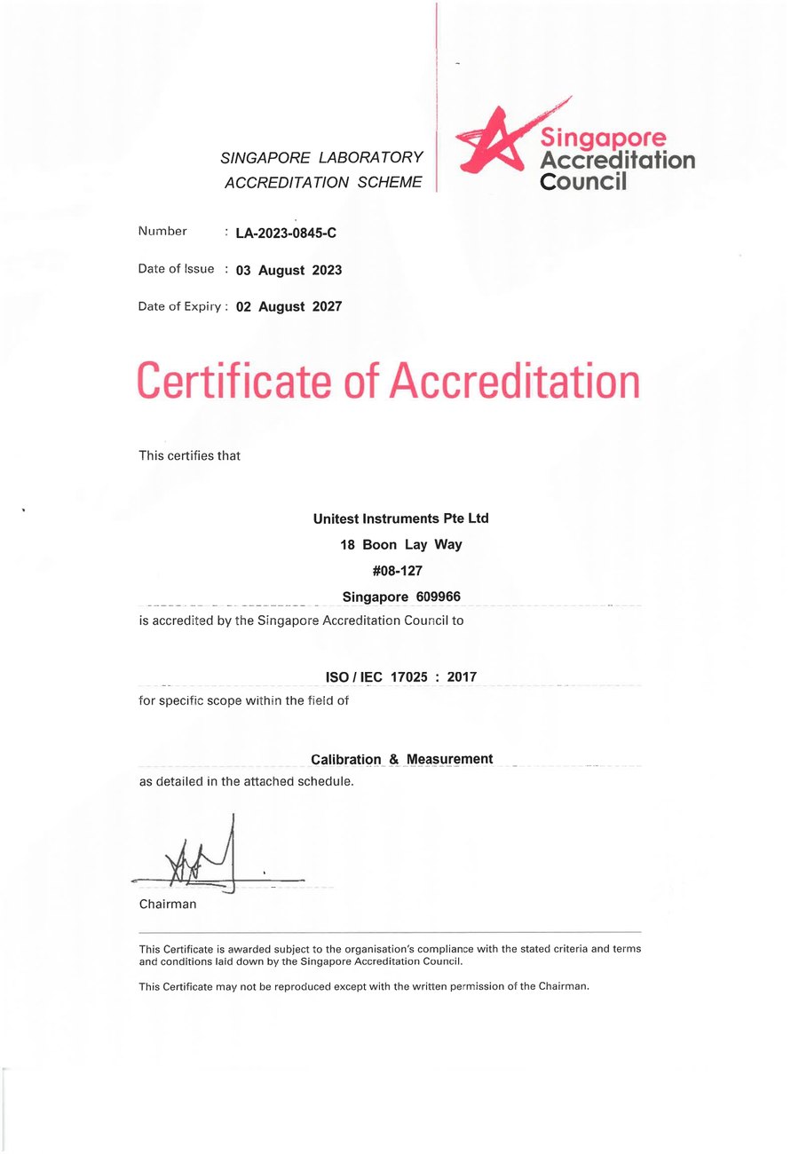
SAC-SINGLAS accredited calibration laboratory (Acc. No. LA-2023-0845-C) serving Singapore's telecom, semiconductor, and industrial sectors. All content reflects our ISO/IEC 17025 accredited scope and is reviewed by our technical calibration team.
Need RF test equipment calibrated by a lab that gets the details right?
Unitest Instruments is SAC-SINGLAS accredited (Acc. No. LA-2023-0845-C) to ISO/IEC 17025. Full frequency-sweep RF calibration, documented uncertainty budgets, certificates accepted by ISO 9001 auditors.