
Key Takeaways
- Gauge blocks are the primary physical length reference in dimensional metrology, calibrated at the highest level by interferometry against a stabilised light wavelength.
- The comparator method calibrates working gauge blocks and other instruments by direct comparison against a higher-grade reference block, rather than by absolute interferometric measurement.
- CMM performance is verified across its working volume using calibrated length artefacts, following the acceptance and reverification concepts in the ISO 10360 family and the measurement uncertainty framework in VDI/VDE 2617.
- The internationally standard reference temperature for dimensional measurement is 20°C. Thermal expansion must be accounted for or controlled at any other temperature.
- Measurement uncertainty, evaluated using the GUM (ISO/IEC Guide 98-3) framework, must accompany every calibration result to make it meaningful.
Gauge Blocks: The Foundation of Length Metrology
Gauge blocks (sometimes called slip gauges or Johansson blocks, after their originator) are the practical building block of dimensional metrology. Each block is a rectangular piece of hardened steel, tungsten carbide, or ceramic, lapped and polished so that two opposing faces are flat to within tens of nanometres and parallel to an extremely tight tolerance. Their defining property is wringing: when two clean, flat gauge block faces are slid together under light pressure, molecular adhesion (assisted by a thin film of air and oil) causes them to stick together as if they were a single solid block, with negligible added length at the interface. This allows a small set of blocks (commonly 47 or 87 pieces), to be combined in different combinations to build up almost any length within their range to sub-micrometre accuracy.
Gauge blocks are graded by accuracy class (commonly K, 0, 1, and 2 under ISO 3650, from tightest to loosest), with the highest grades reserved for calibration laboratory reference sets and the working grades used on the shop floor for instrument calibration and setting. A laboratory's own reference gauge block set is itself periodically calibrated against a national metrology institute, forming the top of the calibration pyramid for essentially all length-related measurement in a given country or region.
Material choice for a gauge block set is itself a genuine engineering decision, not an arbitrary preference. Steel blocks are the traditional standard, relatively low-cost and well-characterised, but they are susceptible to corrosion if handling and storage discipline lapses, and their surface can wear measurably with heavy use over years. Tungsten carbide blocks resist wear far better, making them the preferred choice for working sets subjected to frequent use on a shop floor, at a materially higher purchase cost. Ceramic (typically zirconia) blocks offer the best long-term dimensional stability and corrosion resistance of the three, and are increasingly favoured for laboratory reference sets precisely because their length is less likely to drift over the years between recalibration cycles, though they are also the most brittle and require the most careful handling to avoid chipping an edge.
Interferometry: Measuring Length with Light
At the highest level of accuracy, individual gauge blocks are calibrated by interferometry. A stabilised light source (typically a helium-neon laser locked to a known, extremely stable wavelength), is directed onto the gauge block's measuring face, which has been wrung to an optical flat of known reflectivity. The reflected light from the gauge block surface interferes with light reflected from the reference flat, producing a pattern of alternating bright and dark bands (fringes). Because the wavelength of the stabilised light source is known to extremely high precision, counting the fringe pattern and its fractional offset allows the gauge block's length to be calculated directly from a fundamental physical constant rather than from comparison with another physical artefact.
This is the practical way the metre (defined since 1983 in terms of the speed of light), is disseminated into a usable physical length standard. Interferometric calibration achieves uncertainties measured in tens of nanometres for the shortest, most stable gauge blocks, making it the reference method that all other dimensional calibration ultimately traces back to.
The Comparator Method
Interferometry is precise but slow and impractical for calibrating an entire working gauge block set, let alone routine shop-floor instruments. Instead, most gauge block and length calibration is performed by the comparator method: a length comparator (a highly sensitive mechanical or electronic gauge, typically resolving to 0.01 µm or better) measures the small difference in length between an unknown gauge block and a reference block of certified length. Because only the difference is measured (not the absolute length), the comparator method is fast, repeatable, and well suited to calibrating full sets of working gauge blocks, as well as calipers, micrometers, and other length instruments against a wrung gauge block stack.
| Method | Basis of Measurement | Typical Use | Relative Uncertainty |
|---|---|---|---|
| Interferometry | Light wavelength (absolute) | Reference gauge block calibration at national/top-tier labs | Lowest (best) |
| Mechanical/electronic comparator | Comparison against a reference block | Routine gauge block set and instrument calibration | Low |
| CMM verification (ISO 10360 concept) | Calibrated artefact measured across the working volume | Confirming CMM performance against MPE spec | Depends on artefact & CMM |
| Direct comparison (calipers/micrometers) | Instrument reading vs gauge block reference | Shop-floor instrument calibration | Moderate |
Need gauge blocks, comparators, or CMM-related instruments calibrated?
Unitest Instruments performs traceable dimensional calibration using reference standards maintained under our accredited ISO/IEC 17025 scope, with certificates traceable to Singapore's NMC.
Form Measurement: Roundness, Flatness, and Surface Plates
Length is only one dimensional quantity that matters in manufacturing; geometric form (whether a surface is genuinely flat, a bore is genuinely round, or a shaft is genuinely straight) is equally critical for parts that must seal, rotate, or fit precisely against a mating surface. Form measurement uses different reference standards and instruments from simple length calibration, and understanding these methods rounds out the full picture of dimensional metrology practice.
Flatness is most commonly assessed against a granite or cast-iron surface plate, itself calibrated using either an autocollimator (an optical instrument that measures angular deviation as a straightedge or reference is moved across the plate's surface) or an electronic level survey following a defined grid pattern across the plate. Surface plates are graded by accuracy (commonly AA, A, and B grades under federal and ISO conventions), and, like gauge blocks, a laboratory's own reference surface plate must itself be periodically recalibrated, since granite plates do wear measurably over years of use, particularly in high-traffic areas near the plate's centre where most inspection work is performed.
Roundness measurement uses a dedicated roundness (or roundness/form) measuring instrument, which rotates a part on a precision spindle while a sensitive probe tracks radial deviation as the part turns, producing a polar plot of the part's actual form against a perfect circle. These instruments are calibrated using a certified roundness reference artefact, typically a precision sphere or cylinder with known, extremely small out-of-roundness, and the instrument's own spindle error (the small, inherent wobble of even a very high-precision rotating spindle) must be separated mathematically from the part's actual form error, a technique generally referred to as reversal or multi-step measurement. Getting this separation right is technically demanding, and it is one of the areas where an accredited laboratory's documented, assessed competence genuinely differs from an in-house check performed without the same rigour.
CMM Acceptance and Verification Testing
A coordinate measuring machine is a far more complex instrument than a caliper or gauge block, and its accuracy cannot be reduced to a single number the way a gauge block's length can. Instead, CMM performance is checked by acceptance testing (when the machine is new or has been substantially reworked) and periodic verification testing (ongoing confirmation that it still performs within specification), using the general concepts described in the ISO 10360 family of standards.
These tests typically involve measuring calibrated length artefacts (precision gauge blocks, step gauges, or ball bars), placed in multiple positions and orientations throughout the CMM's working volume, since a CMM's error can vary depending on where in its travel a measurement is taken. The results are compared against the machine's stated Maximum Permissible Error (MPE), often expressed as a formula combining a fixed term and a length-dependent term (for example, in the general form E = A + L/K, where A is a fixed micrometre value, L is the measured length, and K is a scaling constant). If the CMM measures within its MPE across the tested positions, it is considered verified for use within that stated accuracy.
The general measurement uncertainty concept for CMM measurement task-specific uncertainty is described in VDI/VDE 2617, a widely referenced German guideline that complements the ISO 10360 acceptance/verification framework by addressing how uncertainty varies with the specific part geometry and measurement strategy being used. Not just the machine's baseline specification.
Environmental Control: Why 20°C Is the Reference Temperature
Length is not a fixed property of a material. It changes with temperature due to thermal expansion. Dimensional metrology standards internationally reference 20°C as the standard temperature at which length measurements are defined, a convention that traces back to early 20th-century industrial standardisation efforts. A calibration laboratory's dimensional measurement room is typically controlled to 20°C ± 0.5°C or tighter, with both the reference standards and the item under test allowed to reach thermal equilibrium with the room before measurement begins. A process called soaking or stabilisation, which can take anywhere from thirty minutes to several hours depending on the mass and material of the item.
The magnitude of thermal expansion is described by a material's coefficient of thermal expansion (CTE), typically expressed in µm/m/°C. Steel has a CTE of roughly 11.7 µm/m/°C; aluminium is roughly double that, at around 23 µm/m/°C. A 100 mm steel gauge block measured 5°C away from the 20°C reference temperature will differ in length by approximately 100 mm × 11.7 µm/m/°C × 5°C = 0.00585 mm. Small in absolute terms, but significant relative to the tolerance of a precision gauge block or a tight-tolerance machined part. When the workpiece and the measuring instrument are made of different materials with different CTEs, the mismatch compounds further, which is why calibration laboratories match reference standard material where practical and always record the ambient temperature during measurement.
Measurement Uncertainty: The GUM Framework
No measurement is perfectly exact. Every measured value carries some doubt about how close it is to the true value. Measurement uncertainty is the internationally standardised way of quantifying that doubt. The Guide to the Expression of Uncertainty in Measurement, published jointly by several international standards bodies and adopted as ISO/IEC Guide 98-3 (commonly referred to as the "GUM"), provides the accepted framework for identifying every source of uncertainty in a measurement. The reference standard's own calibration uncertainty, the instrument's resolution and repeatability, environmental effects, and operator technique, and combining them mathematically into a single expanded uncertainty figure, typically reported at a 95% confidence level (a coverage factor of k=2).
This concept underpins every accredited calibration certificate: a length isn't just reported as "50.002 mm," it is reported as "50.002 mm ± 0.0015 mm (k=2)," meaning the laboratory is stating, with roughly 95% confidence, that the true length lies within that band. Our companion article on measurement uncertainty explained covers how this figure is built up and interpreted in more everyday terms. Without a stated uncertainty, a dimensional measurement result cannot be meaningfully compared against a tolerance specification, because there is no way to know how much confidence to place in it.
A concept closely related to uncertainty, and one that deserves specific mention, is the guard band. Because a calibration result always carries some uncertainty, a laboratory reporting a pass or fail decision against a tolerance must decide how to treat measurements that fall close to the tolerance limit, within the uncertainty band itself. A guard-banding approach shrinks the effective acceptance limit by the measurement uncertainty, so that a result is only reported as a firm "pass" if it falls within tolerance even after accounting for the uncertainty of the measurement itself, rather than simply comparing the raw reading against the raw tolerance limit. This is standard practice under ISO/IEC 17025 (specifically the 2017 revision's requirement for a documented decision rule) and it is why two calibration providers measuring the identical part can sometimes report different pass/fail conclusions near a tolerance boundary, even when their raw measured values agree closely, because their decision rules for handling borderline results differ.
Reference Artefact Selection: Matching the Standard to the Task
A subtlety often missed outside specialist metrology circles is that the choice of reference artefact used to verify an instrument should reflect the actual measurement task, not simply be "the most accurate standard available." A step gauge used to verify a CMM's linear positioning accuracy, for example, should ideally be made from a material with a thermal expansion coefficient similar to the parts the CMM will actually measure in production, so that any residual temperature control imperfections in the measurement room affect the reference artefact and the production parts similarly, rather than introducing a systematic bias specific to one material combination.
Similarly, the length and orientation of reference artefacts used in CMM verification should span the range and directions genuinely representative of the parts being inspected in service, rather than only testing at a single convenient length or along a single machine axis. An accredited laboratory's ISO/IEC 17025 quality system requires this kind of task-appropriate method selection to be documented and justified, which is part of what the accreditation assessment is actually reviewing when it examines a laboratory's technical procedures, not simply confirming that expensive equipment is present on the premises.
Surface Roughness: A Different Scale of Measurement Entirely
Surface roughness (or surface texture) measurement operates at a scale below general dimensional tolerance, typically in the micrometre and sub-micrometre range, and uses its own dedicated instrumentation and calibration methods rather than the gauge-block-based chain that underpins length measurement. A contact stylus profilometer drags a very fine diamond stylus (with a tip radius often around 2 micrometres) across a surface, recording the vertical deflection as it traces the microscopic peaks and valleys that constitute the surface texture, and reports standard parameters such as Ra (arithmetical mean roughness) or Rz (mean roughness depth) that summarise this texture as a single comparable number.
Calibrating a surface roughness instrument requires certified roughness reference specimens, precision-manufactured surfaces with a known, certified Ra or Rz value, against which the profilometer's stylus and processing electronics are verified. Because surface roughness parameters are calculated using specific filtering and averaging algorithms defined in standards such as ISO 4287 and ISO 21920, calibration also implicitly verifies that the instrument's software is applying these calculations correctly, not just that the mechanical stylus system is accurate. This is a distinct competency from general length or form calibration, and not every dimensional calibration laboratory holds accredited scope for surface roughness, which is worth checking specifically if this parameter matters to your quality system.
How These Methods Connect to Traceability
Interferometry, the comparator method, and CMM verification testing are not independent techniques, they form a connected chain. A national metrology institute realises the metre by interferometry and maintains master gauge blocks calibrated by that method. Accredited laboratories calibrate their own reference gauge block sets against those national masters, typically using interferometric or very high-grade comparator methods. Those laboratory reference sets are then used, via the comparator method, to calibrate a workshop's working gauge blocks, calipers, micrometers, and CMM verification artefacts. Every link carries its own contribution to the overall measurement uncertainty, and every link must be documented for the chain to constitute genuine traceability. A concept explored fully in our article on the traceability chain explained.
Frequently Asked Questions
Gauge blocks are precision-ground blocks of steel, tungsten carbide, or ceramic with two extremely flat, parallel faces separated by a tightly controlled length. Their stability, flatness, and the fact that they can be "wrung" together to build up combined lengths make them the practical, physical realisation of length used to calibrate nearly every other dimensional instrument, from calipers to CMMs. National metrology institutes calibrate their own master gauge block sets by interferometry, and those sets cascade downward through accredited laboratories to workshop-level instruments.
Interferometry measures length by comparing a gauge block's length to the wavelength of a highly stable light source, typically a stabilised laser. When light reflects off the gauge block's measuring face and a reference optical flat, the two beams interfere, producing a pattern of bright and dark fringes. Counting these fringes gives the gauge block's length in units of the known wavelength, with sub-nanometre resolution. This is the highest-accuracy method available for calibrating the shortest, most stable gauge blocks and is how national metrology institutes realise the practical length scale from the SI metre.
The comparator method calibrates a gauge block by directly comparing it against a reference gauge block of known, certified length using a mechanical or electronic length comparator with a high-resolution probe. The comparator measures the small difference between the unknown block and the reference block rather than measuring absolute length directly. This method is faster and more practical for routine calibration of working gauge block sets than interferometry, though it inherits the uncertainty of the reference block used.
Coordinate measuring machine (CMM) verification testing checks that a CMM's overall measuring performance meets its specified accuracy across its working volume. This generally follows the concepts described in the ISO 10360 family of standards, which define acceptance and reverification tests using calibrated length artefacts (such as gauge blocks or step gauges) measured in multiple positions and orientations throughout the machine's volume, alongside the general measurement uncertainty concepts described in VDI/VDE 2617. The result is a maximum permissible error (MPE) specification the CMM is verified against, rather than a single-point calibration.
Nearly all materials expand and contract with temperature, so a workpiece and the instrument measuring it will both change length slightly as temperature varies. Dimensional metrology standards reference 20°C as the standard temperature for length measurement, and accredited laboratories control their calibration environment tightly around this point. A steel part measuring 100 mm at 20°C will measure roughly 0.0117 mm longer at 30°C, using a typical thermal expansion coefficient of 11.7 µm/m/°C for steel. A small but significant error at precision tolerance levels.
Measurement uncertainty is a quantified range, associated with a stated level of confidence, within which the true value of a measurement is believed to lie. In dimensional calibration, uncertainty accounts for contributions such as the reference standard's own uncertainty, the instrument's resolution and repeatability, and environmental factors like temperature. The internationally recognised framework for evaluating and expressing this is described in the Guide to the Expression of Uncertainty in Measurement (GUM), published as ISO/IEC Guide 98-3. Every accredited calibration certificate must state the measurement uncertainty alongside the result.
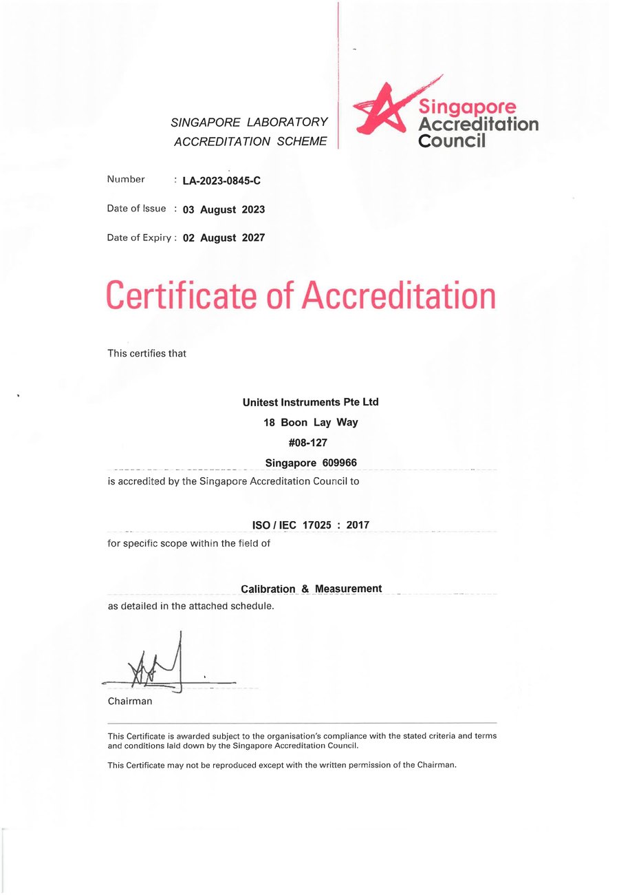
SAC-SINGLAS accredited calibration laboratory (Acc. No. LA-2023-0845-C) serving Singapore's industrial, pharmaceutical, and manufacturing sectors. All content reflects our ISO/IEC 17025 accredited scope and is reviewed by our technical calibration team.
Need traceable dimensional calibration in Singapore?
Unitest Instruments is SAC-SINGLAS accredited (Acc. No. LA-2023-0845-C) to ISO/IEC 17025. Certificates traceable to Singapore's NMC, accepted by ISO 9001 auditors.