
Key Takeaways
- Cosine error from a misaligned measuring axis can silently distort readings even on a perfectly calibrated instrument.
- Temperature differences of just a few degrees between a workpiece and the measuring instrument can produce errors larger than the tolerance band on precision parts.
- Inconsistent measuring force (squeezing a caliper or micrometer too hard), is one of the most common and least discussed sources of operator-induced error.
- Gauge blocks and other reference standards wear with use and require periodic recalibration to catch wear-related drift before it corrupts downstream measurements.
- A calibration certificate is a statement of accuracy on a specific date, not a permanent guarantee. Instruments drift between calibrations from wear, shock, and contamination.
Misconception 1: "A Calibrated Instrument Is Always Accurate"
The single most common misconception in dimensional metrology is treating calibration as a one-time guarantee rather than a snapshot in time. A calibration certificate documents the instrument's error at the moment it was tested. Between calibrations, an instrument is exposed to wear, mechanical shock (drops, rough handling), contamination (swarf, coolant, dust ingress), and material aging. All of which can shift its accuracy without any visible sign of damage.
The practical implication is that calibration intervals matter as much as the calibration event itself. A caliper used heavily on a busy production floor accumulates wear faster than one used occasionally in a controlled lab, and its interval should reflect that. Our guide on how to determine calibration intervals covers the risk-based approach to setting these appropriately.
Cosine Error: The Silent Alignment Problem
Cosine error occurs whenever the axis along which an instrument measures is not perfectly parallel to the true dimension being measured. The measured value is reduced by a factor of cos(θ), where θ is the misalignment angle. Because cosine changes very slowly near zero degrees, small misalignments (a few degrees) produce deceptively small-looking but real errors, and because the error always makes the reading appear smaller than the true dimension, it is easy for an operator to miss.
For example, a caliper measuring a 100 mm length with the jaws tilted just 3° off-axis introduces an error of 100 × (1 − cos 3°) ≈ 0.14 mm. More than ten times the resolution of a typical digital caliper, and enough to fail many precision-machined parts. Cosine error is a technique issue, not an instrument fault, which is why operator training is as important to measurement quality as the calibration programme itself.
Worried your dimensional readings might be drifting?
Unitest Instruments provides accredited dimensional calibration and can advise on technique, interval-setting, and uncertainty budgeting alongside your certificate.
Thermal Expansion: Underestimated at Every Scale
It is easy to underestimate how much temperature affects dimensional measurement because the effect is invisible and the numbers feel small in isolation. Steel expands roughly 11.5 parts per million per °C. That sounds negligible until applied to a real part: a 500 mm steel component changes length by almost 6 micrometres for a 1°C shift. Comparable to, or larger than, the entire tolerance band on many precision-machined features.
A common failure mode is measuring a workpiece immediately after it comes off a machining operation, while it is still several degrees warmer than the 20°C reference temperature (per ISO 1) used for the part's design tolerance. The measurement will read larger than the part's true "cold" dimension, potentially causing a good part to be scrapped, or worse, allowing an undersized part to pass because it happened to be measured cold. Allowing adequate thermal soak time before critical measurements is a simple but frequently skipped step.
Inconsistent Measuring Force
Both calipers and micrometers rely on physical contact between the instrument's measuring faces and the workpiece, and the force applied at that contact point affects the reading. Particularly on softer materials or thin-walled parts, which can deform slightly under excessive clamping force. Many digital micrometers include a ratchet stop or friction thimble specifically to standardise measuring force between operators and readings; skipping this mechanism (tightening by the main thimble instead) is a common source of inconsistent, operator-dependent results.
| Error Source | Typical Cause | Mitigation |
|---|---|---|
| Cosine error | Misaligned measuring axis | Operator training; use of alignment fixtures |
| Thermal mismatch | Warm workpiece measured against room-temp reference | Allow thermal soak time before critical measurements |
| Measuring force variation | Manual clamping without ratchet/friction stop | Use ratchet thimble; standardise technique |
| Reference wear | Repeated wringing/handling of gauge blocks | Periodic recalibration; reserve high grades for lab use |
| Parallax | Viewing an analog scale off-axis | Prefer digital readouts; view scales perpendicular to face |
Misconception 2: "Passing Inspection" Always Means "In Tolerance"
Because every measurement carries an uncertainty, a part measured exactly at the tolerance limit could genuinely be slightly out of tolerance once that uncertainty is accounted for. This is the concept behind guard banding. Tightening the effective accept/reject decision limits inward from the drawing tolerance by an amount related to the measurement uncertainty, so that a borderline reading is not falsely accepted as conforming. Quality teams that treat the drawing tolerance and the measurement decision limit as identical are exposed to a higher risk of false acceptance than they may realise.
Misconception 3: "A More Expensive Instrument Is Automatically More Accurate"
A premium CMM or digital micrometer has a tighter specified accuracy than a basic model, but that specification only holds when the instrument is properly calibrated, used within its intended measuring range, operated with correct technique, and kept in good mechanical condition. A high-end micrometer used with excessive force, contaminated measuring faces, or on a part far outside 20°C can easily produce a worse result than a correctly used, properly calibrated mid-range instrument. Instrument quality sets the ceiling on achievable accuracy; calibration, technique, and environmental control determine whether that ceiling is actually reached.
Abbe error: the misalignment cost hidden in instrument design
Abbe error occurs when the scale being read is not in line with the axis of the measurement being taken, and it is one of the least understood sources of dimensional error because it does not show up as an obvious mistake, it is built into certain instrument geometries by design. A caliper is the classic example: its scale sits offset from the jaws doing the actual measuring, so any looseness or flex in the slide mechanism translates into a measurement error that grows with the size of the part being measured. A micrometer, by contrast, has its scale (the spindle's thread) directly in line with the measurement axis, which is a major reason micrometers achieve tighter accuracy than calipers of comparable price even though both instruments measure the same basic quantity. This is not a defect in caliper design, it is an inherent geometric limitation, and it is why calipers are specified for lower-precision applications while micrometers or CMMs are specified where Abbe-error-free measurement genuinely matters to the tolerance involved.
Parallax error in analogue and dial instruments
Where a measurement is read visually against a scale or dial rather than displayed digitally, the angle from which the operator views the reading introduces parallax error, an apparent shift in the reading caused by viewing the scale from anything other than directly perpendicular to its face. On a dial indicator or a vernier caliper's analogue scale, viewing from even a slight angle can introduce a reading error that is entirely separate from the instrument's own calibrated accuracy. This error disappears with digital instruments, which is one of the practical (not merely convenience-driven) reasons digital calipers and micrometers have become the default in many production environments. Where analogue instruments remain in use, correct viewing technique, positioning the eye directly perpendicular to the scale, is a real, trainable factor in measurement quality, not merely a nicety.
Surface contamination and its effect on measured results
Dust, oil film, or swarf on either the measuring faces of an instrument or the surface of the part being measured introduces a real, physical offset into the reading, since the instrument is now measuring the combined thickness of the part plus whatever contamination sits between the measuring faces and the true surface. This sounds obvious stated directly, but it is a frequent, quiet source of measurement drift on a busy shop floor, where instruments handled repeatedly without cleaning accumulate a film that gradually shifts every subsequent reading in the same direction. Reference standards are especially sensitive to this: a gauge block with any contamination on its wringing surfaces will not only measure incorrectly itself but can transfer that error to every instrument subsequently calibrated against it that session. Simple, disciplined cleaning practice before each measurement session is a genuinely effective, low-cost error reduction measure that gets overlooked precisely because it seems too basic to matter.
Operator repeatability and why Gauge R&R exists
Even with a correctly calibrated instrument, held at the correct temperature, free of contamination, different operators (and the same operator on different occasions) will produce slightly different readings of the identical part, due to differences in applied force, alignment technique, and reading interpretation. This operator-introduced variation is what Gauge Repeatability and Reproducibility (Gauge R&R) studies are designed to quantify: repeatability captures the variation from the same operator measuring the same part repeatedly, reproducibility captures the variation between different operators measuring the same part. A measurement system with excellent instrument accuracy but poor Gauge R&R performance can still produce unreliable production decisions, because the variation introduced by who is doing the measuring exceeds what the process tolerance can absorb. This is a distinct exercise from instrument calibration (which verifies the instrument against a reference standard) and is increasingly expected as a companion practice under IATF 16949 and other production-quality frameworks, precisely because calibration alone does not capture this human factor in the measurement chain.
Applied measuring force: why "just tighten it down" is wrong
Every contact-based dimensional instrument, calipers, micrometers, and mechanical comparators alike, deforms the part being measured, and itself, slightly under the applied measuring force, and inconsistent force between measurements is a genuine, quantifiable source of error rather than a minor technique detail. Micrometers address this directly through a ratchet stop or friction thimble mechanism, designed to slip once a consistent, calibrated force is reached, specifically so different operators (or the same operator at different times) apply the same measuring force rather than whatever force feels right by hand. Calipers, lacking this mechanism on most standard designs, are considerably more exposed to this error source, since the operator's own judgement of "snug" varies meaningfully between individuals and even between measurements by the same person on different days. For genuinely tight-tolerance work, this is one of several reasons a micrometer with its calibrated force mechanism is specified over a caliper even where the two nominally offer comparable resolution on their digital displays; the caliper's resolution figure does not capture the additional force-related variability its design does nothing to control.
Instrument wear: measuring faces, backlash, and why old instruments read differently
An instrument that was accurately calibrated when new does not necessarily remain equally accurate simply because it has not been dropped or obviously damaged; the measuring faces of calipers and micrometers wear gradually with normal use, particularly on production floors where the same instrument measures thousands of parts over its service life. Worn measuring faces can introduce a small but real flatness or parallelism error between the two contact surfaces, which shows up as an instrument that measures consistently but slightly incorrectly across its range, exactly the kind of error a routine calibration check is designed to catch through as-found deviation data. Mechanical backlash, play introduced in the threaded spindle mechanism of a micrometer or in the sliding mechanism of a caliper as internal components wear, is a related but distinct issue: it can cause a measurement to read differently depending on whether the spindle or jaw was approached from an opening or closing direction, an error a competent as-found calibration check specifically tests for by taking readings in both directions. Neither wear mode is a defect exactly, it is normal ageing, but it is precisely why a fixed calibration interval based on age or usage, reviewed against genuine as-found drift data, matters more for heavily used shop-floor instruments than for a rarely used reference tool sitting mostly idle in a drawer.
CMM-specific error sources: probing force and stylus deflection
Coordinate measuring machines introduce error sources with no equivalent in handheld instruments, given their more complex probing and multi-axis measurement process. Probing force, the contact force applied when the CMM's probe tip touches the part surface to register a measurement point, must be low enough to avoid deforming delicate parts or deflecting a long, thin probe stylus, yet consistent enough to register a repeatable trigger point; modern touch-trigger and scanning probe systems are specifically engineered to manage this trade-off, but stylus deflection remains a real, characterisable error source that grows with stylus length, which is why CMM programmers generally specify the shortest practical stylus length for a given feature access requirement rather than defaulting to a longer, more flexible stylus for convenience. Probe qualification, a routine procedure run before a CMM measurement programme where the probe is used to measure a calibrated reference sphere from multiple approach angles, exists specifically to characterise and compensate for these geometry-dependent effects before they propagate into actual part measurements, and is itself a form of interim verification distinct from, but complementary to, the CMM's own periodic full volumetric calibration.
Surface plate and reference surface errors
Many dimensional measurements are made relative to a reference surface, a granite or cast iron surface plate providing the flat datum against which height gauges, dial indicators, and comparators take their readings, and the surface plate's own flatness and condition is itself a real source of error if neglected. Surface plates wear unevenly with use, accumulating more wear in the central area where most measurements are typically taken, and this localised wear introduces a genuine flatness deviation that a periodic calibration check (typically using precision levels or an autocollimator to map the surface) is specifically designed to catch. Contamination, dust, grit, or a stray chip left on the surface, introduces the same kind of physical offset error discussed for measuring faces earlier, magnified by the fact that an entire measurement setup, not just a single instrument, is referenced against the compromised surface. Treating a surface plate as a precision reference standard requiring its own periodic calibration and disciplined cleaning practice, rather than as inert workshop furniture, is a distinction that materially affects the accuracy of every measurement taken against it.
Vibration and its effect on precision measurement
External vibration, from nearby machinery, forklift traffic, or even a busy factory floor's general activity, transmits through a surface plate or workbench into whatever instrument is taking a measurement, and for sufficiently precise work, this vibration is itself a real source of measurement uncertainty. Coarse hand tools like calipers are relatively insensitive to typical workshop vibration levels, but sensitive comparators, electronic height gauges, and especially CMMs operating at their tightest achievable accuracy can show genuinely degraded repeatability in a vibration-heavy environment. This is why precision dimensional metrology laboratories, including accredited calibration labs performing reference-grade work, commonly isolate their most sensitive equipment on vibration-damping mounts or dedicated foundations separate from the general building structure, and why a CMM installed directly on a production floor near heavy machinery, however convenient for production access, may show measurably worse repeatability than the identical machine installed in a quieter, vibration-isolated location. For genuinely tight-tolerance work, the measurement environment's vibration profile deserves the same deliberate consideration as its temperature control, rather than being an afterthought addressed only if repeatability problems are later observed.
Frequently Asked Questions
Cosine error occurs when a measuring instrument's axis of measurement is not perfectly aligned with the direction of the dimension being measured. The reading is reduced by a factor of the cosine of the misalignment angle, so even a small angular offset (a few degrees), can introduce a measurable error, particularly over longer measurement lengths. It is one of the most common operator-technique errors in caliper and micrometer use.
Yes. Steel expands approximately 11.5 parts per million per degree Celsius, meaning a 500 mm steel part changes length by nearly 6 micrometres for a 1°C temperature shift. For measurements with tolerances in the tens-of-micron range, a temperature difference of just a few degrees between the workpiece and the measuring instrument can produce an error larger than the tolerance band itself.
Not necessarily, and this is a common misconception. An instrument's specified accuracy only applies when it is properly calibrated, used within its intended range, operated with correct technique, and maintained in good condition. A premium micrometer used with excessive measuring force or worn anvils can produce worse results than a properly calibrated, correctly used mid-range instrument.
Yes, gauge blocks wear with use, particularly from repeated wringing and handling, which can gradually alter their calibrated length and degrade their flatness and parallelism. This is why reference-grade (Grade K) blocks are typically reserved for laboratory calibration work rather than daily shop-floor use, and why gauge block sets require periodic recalibration to detect wear-related drift.
Not always, when measurement uncertainty is taken into account. A part measuring exactly at the tolerance limit could genuinely be slightly out of tolerance once the measurement's own uncertainty is considered. This is the basis of "guard banding". Tightening the effective accept/reject limits by an amount related to the measurement uncertainty, so borderline results are not falsely accepted.
No. Measuring instruments drift over time due to wear, mechanical shock, contamination, and material aging, even with careful use. This is why calibration is performed at defined intervals rather than once, and why a calibration certificate always states a specific calibration date. It is a statement of accuracy at that point in time, not a permanent guarantee.
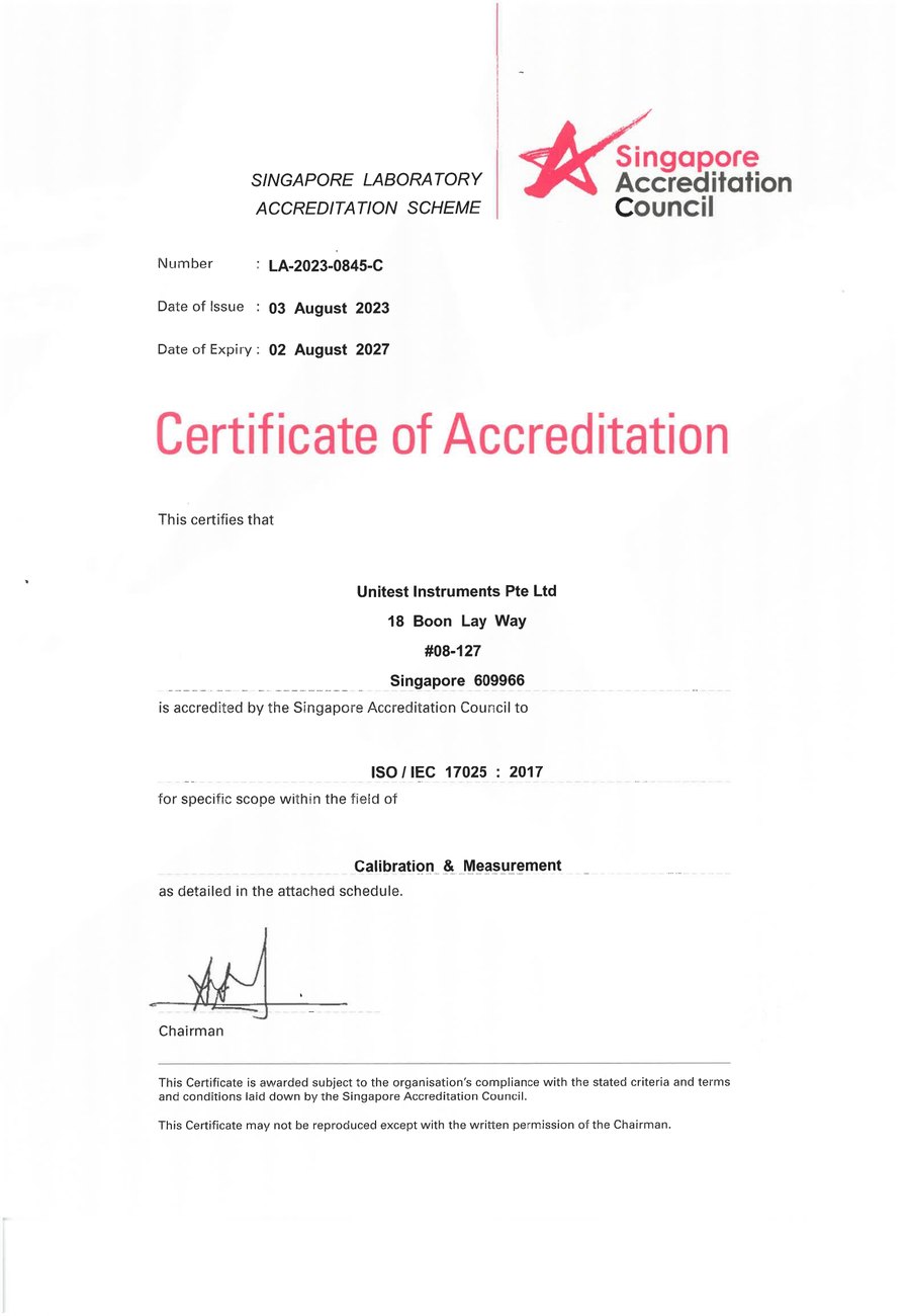
SAC-SINGLAS accredited calibration laboratory (Acc. No. LA-2023-0845-C) serving Singapore's industrial, pharmaceutical, and manufacturing sectors. All content reflects our ISO/IEC 17025 accredited scope and is reviewed by our technical calibration team.
Need dimensional instrument calibration in Singapore?
Unitest Instruments is SAC-SINGLAS accredited (Acc. No. LA-2023-0845-C) to ISO/IEC 17025. Same-week turnaround, certificates accepted by ISO 9001, AS9100, and IATF 16949 auditors.